Traffic Control Systems Handbook: Chapter 6. Detectors
6.1 Introduction
The Traffic Detector Handbook (1) provides a detailed discussion of traffic detectors. Klein (2) also provides extensive information, and was used as a major source in the preparation of this chapter.
Any traffic-responsive control system depends on its ability to sense traffic for local intersection control and / or system-wide adjustment of timing plans. A system accomplishes this by using one or more of the following detector types:
- Pavement Invasive Detectors
- Inductive Loop: Most common detector technology. Consists of one or more turns of insulated loop wire wound in a shallow slot sawed in the pavement. Loop detectors come in different sizes and shapes, and various configurations can be used depending on the area to be detected, the types of vehicles to be detected, and the objective (such as queue detection, vehicle counting, or speed measurements).
- Magnetometer: Measures changes in both the horizontal and vertical components of the earth's magnetic field. Early magnetometers could only detect the vertical component, which made them unable to operate near the equator, where magnetic field lines are horizontal. Newer two-axis fluxgate magnetometers overcome this limitation. Magnetometers are useful on bridge decks and viaducts, where the steel support structure interferes with loop detectors, and loops can weaken the existing structure. Magnetometers are also useful for temporary installations in construction zones.
- Magnetic: Consists of a coil of wire with a highly permeable core. Measures the change in the lines of flux of the earth's magnetic field. Can only detect vehicles moving faster than a certain minimum speed, and therefore can not be used as a presence detector. Useful where pavement cannot be cut, or where deteriorated pavement or frost activity break inductive loop wires.
- Non-pavement invasive detectors
- Microwave Radar: Transmits microwave energy toward the roadway. CW (Continuous Wave) Doppler radar can only detect flow and speed. FMCW (Frequency Modulated Continuous Wave) radar can also act as presence detector. Certain bridges with large steel structures can cause problems with radar based systems.
- Active Infrared: Transmits infrared energy from detector and detects the waves that are reflected back.
- Passive Infrared: Does not transmit any energy; detects energy from vehicles, roadway and other objects, as well as energy from the sun that is reflected by vehicles, roadway, and other objects.
- Ultrasonic: Transmits ultrasonic sound energy waves, and measures the distance that the reflected wave travels. Can detect vehicle count, presence, and lane occupancy.
- Acoustic: Measure vehicle passage, presence, and speed by passively detecting acoustic energy or audible sounds produced by vehicular traffic.
- Video Image Processor: Video cameras detect traffic, and the images are digitized, processed and converted into traffic data. Can replace several loop detectors, and measure traffic over a limited area, rather than just a single point.
- Specialized detector function
- Bus
- Automatic Vehicle Identification / Electronic Toll and Traffic Management
- Overheight
- Environmental
- Pedestrian
- Pre-emption
A system can use traffic detectors singly or in combination to measure variables such as presence, volume, speed, and occupancy. Occupancy refers to the percentage of time that there is a vehicle over the detector.
Systems use these variables as control parameters at individual signalized intersections, and in other advanced signal control logic.
For local control of intersections, the local controller will:
- Process these outputs,
- Compare processed detector information with some preset control parameter or parameters, and
- Make a decision on intersection phasing and timing.
This chapter discusses detector locations, configurations, and applications.
6.2 Detector Operations Summary
This section describes the detector-controller relationship and techniques for using detectors on low- and high-speed approaches. An understanding of this section will allow appropriate selection of a detector type for a given application. Tables 6-1 and 6-2 compare characteristics of different detector types.
Detector-Controller Relationship
A vital relationship exists between a controller's timing intervals and the detection techniques it employs. The appropriate combination of detector type, placement and controller settings can improve an intersection's efficiency and safety. The following discussion highlights this relationship and is based on Guidelines for Selecting Traffic-Signal Control at Individual Intersections, Vol. II (3).
| Technology | Strengths | Weaknesses |
|---|---|---|
| Inductive Loop |
|
|
| Magnetometer (Two-axis fluxgate magnetometer) |
|
|
| Magnetic (Induction or search coil magnetometer) |
|
|
| Microwave Radar |
|
|
| Active Infrared (Laser radar) |
|
|
| Passive Infrared |
|
|
| Ultrasonic |
|
|
| Acoustic |
|
|
| Video Image Processor |
|
|
| Sensor Technology | Count | Presence | Speed | Output Data Occupancy | Classification | Multiple Lane, Multiple Detection Zone Data | Communication Bandwidth | Sensor Purchase Costa (each in 1999 US $) |
|---|---|---|---|---|---|---|---|---|
| Inductive Loop | • |
• |
•b |
• |
•c |
Low to Moderate | Lowi ($500 - $800) | |
| Magnetometer (two axis fluxgate) | • |
• |
•b |
• |
Low | Moderatei ($900 - $6,300) | ||
| Magnetic Induction Coil | • |
•d |
•b |
• |
Low | Low to moderatei ($385-$2,000) | ||
| Microwave Radar | • |
•e |
• |
•e |
•e |
•e |
Moderate | Low to moderate ($700-$2,000) |
| Active infrared | • |
• |
•f |
• |
• |
• |
Low to Moderate | Moderate to high ($6,500-$3,300) |
| Passive infrared | • |
• |
•f |
• |
Low to Moderate | Low to moderate ($700-$1,200) | ||
| Ultrasonic | • |
• |
• |
Low | Low to moderate (Pulse model: $600-) | |||
| Acoustic Array | • |
• |
• |
• |
•g |
Low to Moderate | Moderate ($3,100-$8,100) | |
| Video Image Processor | • |
• |
• |
• |
• |
• |
Low to High h | Moderate to high ($5,000-$26,000) |
| Notes: a. Installation, maintenance, and repair costs must also be included to arrive at the true cost of a sensor solution as discussed in the text. b. Speed can be measured by using two sensors a known distance apart or estimated from one sensor, the effective detection zone and vehicle lengths. c. With specialized electronics unit containing embedded firmware that classifies vehicles. d. With special sensor layouts and signal processingsoftware. e. With microwave radar sensors that transmit the proper waveform and have appropriate signal processing. f. With multi-detection zone passive or active mode infrared sensors. g. With models that contain appropriate beamforming and signal processing. h. Depends on whether higher-bandwidth raw data, lower-bandwidth processed data, or video imagery is transmitted to the TMC. i. Includes underground sensor and local detector or receiver electronics. Electronics options are available to receive multiple sensor, multiple lane data. |
||||||||
Low-Speed Approaches experience speeds less than 35 mi/hr (56.3 km/hr). Detection system requirements depend on whether the controller unit phase has been set to locking or non-locking detection memory (sometimes termed memory ON or memory OFF, respectively).
Locking Detection Memory enables a controller to remember or hold a vehicle call (even after the calling vehicle leaves the detection area) until satisfied by the appropriate green indication. Locking detection memory often uses small-area or point detection such as a 6- by 6-ft (1.8- by 1.8-m) loop or magnetometer. This approach minimizes detection cost. However, it cannot screen out false calls (such as those occurring with a right turn on red).
Most traffic engineers desire the allowable gap to range from 3 to 4 seconds, which requires locating the detector 3 to 4 seconds of travel time back from the stopline. This approach efficiently positions the detector to accurately time the end of green, after passage of the first vehicle of a queue or platoon.
However, the above technique applies only to low-speed approaches and intersections controlled by an actuated controller (without gap reduction). Using a practical allowable gap of 3 to 4 seconds, the detector setback should not exceed 170 ft (52 m). Some agencies prefer to limit this to 120 ft (37 m). See Table 6-3 for a summary of this principle (1).
| Approach Speed | Detector Set-Back From Stopline to Leading Edge of Inductive Loop Detector | Minimum Green Time (seconds) | Passage Time (seconds) | ||
|---|---|---|---|---|---|
| mi/h | km/h | feet | meters | ||
| 15 | 24 | 40 | 12 | 9 | 3 |
| 20 | 32 | 60 | 18 | 11 | 3 |
| 25 | 40 | 80 | 24 | 12 | 3 |
| 30 | 48 | 100 | 30 | 13 | 3.5 |
| 35 | 56 | 135 | 41 | 14 | 3.5 |
| 40 | 64 | 170 | 52 | 16 | 3.5 |
| Note: For approach speeds greater than 45 mi/h (72 km/h), volume-density or multiple detectors recommended. Volume-density could be considered at speeds of 35 mi/h (56 km/h) or above. | |||||
Non-locking Detection Memory sets phases through loop-occupancy control using large-area presence detectors, such as 6- by 50-ft (1.8- by 15.2-m) loops or multiple magnetometer detectors. In this non-locking mode, the controller phase drops (or forgets) a waiting call when the vehicle leaves the detection zone. This greatly simplified control strategy responds to the presence / non-presence of vehicles. The non-locking feature reduces delay by avoiding diversion of the right-of-way to an empty approach.
Loop-occupancy control was first used at intersections with a separate left-turn control, in addition to locations that permitted right-turn-on-red. In this application, a call placed during the yellow change interval cannot restore the green to an empty approach. Another potential advantage exists at intersections that permit a left-turn during the through movement (permissive left). To enhance this operation, a delay detector unit outputs a call to the controller only if a vehicle is continuously detected beyond a preset time period. The NEMA TS2 specification includes an optional delay / extension capability (4). Other controllers can achieve this capability using appropriate controller software. During light traffic conditions, left-turn and right-turn-on-red vehicles in transit over the loop are detected, but no call is placed until the preselected time delay has expired, thus reducing intersection delay by omitting unnecessary phase changes.
Often, loop-occupancy control is used for through-phase detection on approaches with low-approach speeds. This technique minimizes delay by allowing the use of a short extension interval in the range of 0 to 1.5 seconds.
The length of the detection area depends on the approach speed and the controller timing settings. For approach speeds below 30 mi/hr (48.3 km/hr), Figure 6-2 indicates a detection area length for various unit extension time settings (1). Approach speeds above 35 mi/hr (56 km/hr) require a different technique to alleviate driver indecision caused by the yellow change interval.
L = 1.47 S (3 − PT) − 18 in English units (equation 6-1a)
L = 0.277 S (3 − PT) − 5.5 in metric units (equation 6-1b)
Where
L = length of detection area, ft (m)
S = approach speed, mi/h (km/h)
PT = passage time (unit extension), seconds.
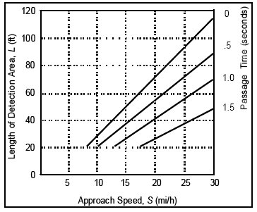
Figure 6-2. Inductive Loop Detector Length for Loop Occupancy Control
High-Speed Approaches experience speeds of 35 mi/hr (56 km/hr) or greater. If the yellow change interval begins with a vehicle in an indecision zone, the driver may have difficulty deciding whether to stop or proceed through. An abrupt stop may produce a rear-end collision, while going through on red may produce a right-angle accident. Table 6-4 shows the boundaries of the dilemma zone, and Figure 6-3 illustrates dilemma zone boundaries for a vehicle approaching an intersection at 40 mi/h (5). The data indicates that the upstream boundary of the dilemma zone, where 90 percent of motorists will decide to stop, lies 4.5 to 5 seconds from the intersection. The lower boundary, where 10 percent of the motorists will decide to stop, is 2 to 2.5 seconds from the intersection. Therefore, the duration of the dilemma zone does not exceed 3 seconds, starting approximately two seconds in advance of the stopline. Figure 6-4 shows one implementation for a high speed approach.
| Approach Speed | Distances from intersection for 90% and 10% probabilities of stopping | ||||
|---|---|---|---|---|---|
| mi/h | km/h | 90% values in ft | 10% values in ft | 90% values in m | 10% values in m |
| 35 | 56 | 254 | 102 | 77 | 31 |
| 40 | 64 | 284 | 122 | 87 | 37 |
| 45 | 72 | 327 | 152 | 100 | 46 |
| 50 | 80 | 353 | 172 | 108 | 52 |
| 55 | 88 | 386 | 234 | 118 | 71 |
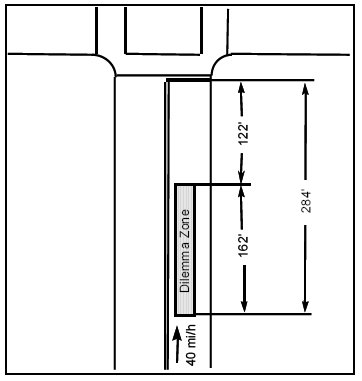
Figure 6-3. Dilemma Zone for Vehicle Approaching an Intersection at 40 mi/h (64 km/h)
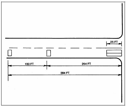
Figure 6-4. Loop Location for Extended Call-Delay Design With 55 mi/hr (88.6 km/hr) Approach Design Speed
An actuated controller with appropriate detection can minimize inappropriate yellow change intervals. A research project examined a number of advanced detector-controller designs for high-speed, isolated approaches (6). Table 6-5 shows conventional detector-controller designs enhanced with multiple-point detection and / or a density-actuated controller (7). For details of the applications of these designs, see Chapters 10 and 11 of Reference 6. Table 6-5 demonstrates various combinations of detector-controller hardware that improve safety at high-speed intersections.
| Type of System | Design | Memory | Detection Type | Controller Comments |
|---|---|---|---|---|
| 1. Green-extension systems for semi-actuated controllers | A. 2-loop B. 3-loop | Locking | Semi-actuated | Composed of extended-call detectors and auxiliary logic units to hold the controller in main street phase A, until the approaching vehicle has cleared the dilemma zone. Vehicles traveling slower than design speed or termination of green by gapout may be trapped in the dilemma zone. Increasing the passage time for protection results in an intolerable allowable gap. |
| 2. Extended-call detection systems for basic controllers | A. Extended-call (EC) design uses 70 ft (21.3 m) loop at the stopline (normal detector output) supplemented by extended-call detector 5 seconds before the stopline | Non-locking | Basic full-actuated | A. The stretch setting on the extended-call detectors requires compromise between rapid operation and protection for slower vehicles. The allowable gap of the EC design is typically 5 seconds because of the stretch detector and long loop at the stopline. Appears limited to routes carrying less than 10,000 ADT. Design has lowest initial cost. operation. |
| B. Extended-call and delayed-call (EC-DC) design uses 25 ft (7.6 m) loop at stopline (delay-call output) supplemented by extension detector 5 seconds before stopline and a third detector between them (see figure 6-4 (8)) | Non-locking | Basic full-actuated | B. A stretch setting of 2.2 seconds on the upstream loop will carry vehicles approaching within the speed range of 40 to 55 mi/hr (64.4 to 88.5 km/hr) through the dilemma zone. A vehicle traveling less than 40 mi/hr (64.4 km/hr) will also be protected because the yellow will appear before the vehicle has reached its dilemma zone. The 2.2 second extension time produces an allowable gap for traffic of 3.8 seconds (55 mi/hr (88.5 km/hr)) and 4.4 seconds (40 mi/hr (64.4 km/hr). The allowable gap is actually greater than the 1 second difference of the EC design. The EC-DC design disables the stopline loops to give a decided superiority to EC design in real-world operation. | |
| 3. Multiple-point detection systems for basic controllers | A. Bierele modified method uses 5 detectors for 55 mi/hr (88.5 km/hr) approach speeds, with farthest detector placed 349 ft (106.4 m) from the stopbar. Uses special detector logic to determine approach speed and disable first 3 loops (see figure 6-5a (9)) | Locking | Basic full-actuated | A. Bierele has modified his design for speeds greater than 40 mi/hr (64.4 km/hr). The first 3 detectors from the stopline are based on 40 mi/hr (64.4 km/hr) speeds and operate on 1 amplifier (speed detector). 2 additional, detectors are placed at 1 second intervals for 40 mi/hr (64.4 km/hr) until a distance of 349 ft (106.4 m) is reached, and tied to the second amplifier (standard detector). For speeds greater than 40 mi/hr (64.4 km/hr), the special detectors are disabled, and only the standard detectors extend the green to maintain a tolerable gap. |
| B. Texas Department of Highways and Public Transportation uses primary loop detector placement designs for 45 to 55 mi/hr (72.5 to 88.5 km/hr) (see figure 6-5a (9)) | Locking | Basic full-actuated | B. This method used AASHTO stopping sight distances (based on 1 second perception-reaction time) for approach speeds up to 55 mi/hr (88.5 km/hr). This design is based on the assumption that a vehicle entering the loop field at the design speed will guarantee a safe stopping distance and a green if the speed is maintained or reduced by no more than 10 mi/hr (16.1 km/hr) between successive loops. | |
| C. Winston-Salem method employs 3 sensors for 50 mi/hr (80.5 km/hr) approach D. SSITE method uses 6 sensors for 50 mi/hr (80.5 km/hr) approach | Locking | Basic full-actuated | C. This method for detector placement is derived from the Bierele method, and uses stopping sight distances computed from the Traffic Engineering Handbook. The outermost point of initial detection is 240 ft (73.2 m) for a 50 mi/hr (80.5 km/hr) approach speed, which may not detect a vehicle before it reaches the dilemma time. Attempts to improve the design in that respect result in an allowable gap that is too long and frequently causes the controller to max-out. | |
| D. SSITE method uses 6 sensors for 50 mi/hr (80.5 km/hr) approach | Non-locking | Basic full-actuated | D. This multisensor design will adequately protect the driver from the dilemma zone, with its farthest detector set back 5 seconds from the stopline. However, with its 2 second vehicle interval, two-50 mi/hr (80.5 km/hr) vehicles will cause an allowable gap of 7 seconds; too long to be a design of choice | |
| 4. Extended-call systems for density controllers | A. Single-point method composed of a presence loop at the stopline and one upstream detector | Non-locking | Density full-actuated | A. This method provides dilemma zone protection to vehicles operating at the design speed. The suggested 2 second vehicle interval may be insufficient for a slower vehicle to enter the usable yellow line. |
| B. Multiple-point method employs a presence loop at the stopline and several upstream sensors | Non-locking | Density full-actuated | B. The multiple-point method can be configured to afford dilemma zone protection for a variety of approach speeds and operating conditions. A queue can get into motion without gapping out and false calls can be screened out because of detection at the stopline. |
6.3 Vehicle Detector Location and Configuration
This section focuses on alternative detector designs and their appropriate application to:
- Isolated actuated intersection control,
- Urban system control, and
- Freeway monitoring and control.
Isolated Actuated Intersection Control
Since vehicle arrivals fluctuate at individual intersections, efficiency depends on responsiveness to minute-by-minute demand variations. The actuated green interval is changeable and can be tailored to actual arrivals. This varying green interval (from minimum to maximum controller settings) is determined by the unit extensions generated by vehicles crossing the detectors. For most volume levels, full actuated control proves to be the most cost-effective method (10). Full vehicle actuation is normally preferable to pretimed or semi-actuated control.
Small-Area Detectors simply detect the passage of a vehicle at a spot location (e.g., upstream of the stopline). Small-area detectors are often called short-loop, point, or passage detectors. The magnetic detector can only be used for point detection because it covers a small area. Short-loop detectors (less than 20 ft (6.1 m) long) are the simplest and most common type.
As previously discussed, small-area loops back from the stopline act as calling detectors for high-speed approaches. Figure 6-5 illustrates a high-speed detector design using multiple short loops (11). Magnetometers also cover small areas. Some agencies use a single 6 ft (1.8 m)-long loop to cover two or more lanes. Single point detection is relatively inexpensive but gives no information on traffic between the downstream detector and stopline. Figure 6-6 illustrates the contrast between small- and large-area detection (10).
Large-Area Detectors, usually long loops, register presence of a vehicle in the detection zone as long as the detector remains occupied. In this mode, the controller holds in the extension interval until the detector clears. Thus, a very short extension interval is used. Figure 6-7 illustrates various detection designs, including both small- and large-area detection (9).
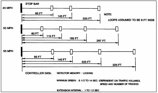
Figure 6-5 (a)
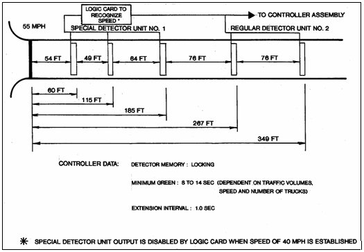
Figure 6-5 (b)
Figure 6-5. Two Methods Of Multiple Point Detection Systems for Approach Speeds Up To 55 mi/hr (88.6 km/hr)
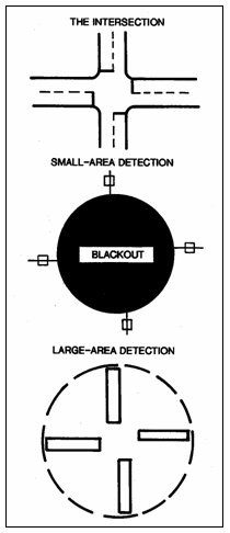
Figure 6-6. Contrast Between Small-Area and Large-Area Detection
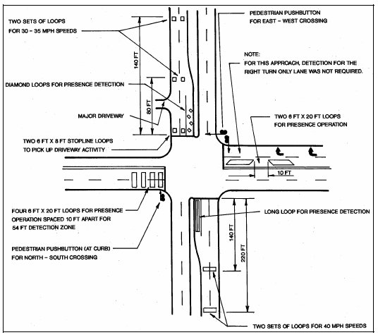
Figure 6-7. Typical Detector Designs
As previously discussed, loop occupancy control uses large-area detection and non-locking detection memory. This design operates best with well-formed platoons on low-speed approaches. However, random vehicles may cause the controller to max-out when vehicle headways permit one vehicle to enter the detection zone just as the previous one leaves. Figure 6-4 shows detector placement for the extended and delayed call (EC-DC) design using large-area detection at the stopline with two small-area detectors upstream for high-speed vehicles (8). This detector configuration has proven very effective.
Disadvantages of large-area detection include:
- Higher installation costs, and
- Greater maintenance problems with long loops.
To reduce long loop problems, use a series of 6-ft (1.8-m) wide loops placed parallel to the stopline and separated by approximately 9 or 10 ft (2.7 or 3.0 m). This design allows:
- Higher loop sensitivity and protection against losing a lane of detection, and
- Operation with one or more failed loops.
Left-Turn Lanes. Efficient vehicle detection in left-turn lanes can increase intersection capacity by reducing lost green time. The Illinois Department of Transportation has designed a loop configuration for left-turn lanes that improves intersection efficiency and safety (12). Efficient presence actuation must account for:
- Driver start-up time averages 3 to 4 seconds for the first vehicle in a queue while headway averages 2 to 3 seconds between following vehicles. Loop length must accommodate longer than average reaction times to maintain green for starting vehicles.
- Trucks and other slow vehicles require a longer start-up time, often leaving a three to four car length (6 to 12 second) gap ahead of them. At locations with a relatively high percentage of trucks, loop length must account for these gaps.
- One or two vehicles require only a short green time. The detection zone length, however, must allow the following car either to reach the loop in time to maintain the green or decelerate to a stop.
- A vehicle extension interval of 1.0 seconds permits drivers to almost complete their turning radius before yellow occurs. Any additional extension becomes lost time. A shorter vehicle extension interval disturbs drivers when the yellow appears.
- A minimum loop length from the stopline of 80 ft (24.4 m).
- Vehicles allowed to turn left on the through green (permissive), normally proceed past the stopline and wait for a gap in the opposing traffic to complete their turns. Lack of a gap can strand the left-turner ahead of the detection zone that ends at the stopline. The controller will then skip the protected left-turn phase in the next cycle, if no other vehicles are waiting to turn left. The driver may complain of a malfunctioning signal resulting in an unnecessary service call. Extending the detection zone beyond the stopline may resolve this problem.
Figure 6-8 shows a minimum left-turn loop design that addresses the above requirements (12).
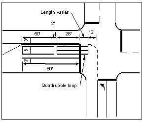
Figure 6-8. Left-turn Detection Inductive Loop Configuration Used By Illinois
The loop layout should include advanced, local actuation detection when:
- Left-turn demand requires storage of 150 ft (45.7 m) or more, or
- Approach speeds require a safe stopping distance.
Advanced detection using a call-extension feature will extend the effective detection zone to accommodate heavy vehicle or truck volumes and provide for safer operation (see Figure 6-9 (12)).
In many instances, one 30 to 40 ft (9 to 12.2 m) presence loop suffices for left-turn detection and provides rapid initiation of the left-turn phase. Left-turn loop design varies with:
- Approach speed,
- Presence of heavy trucks, and
- Grade and intersection geometries.
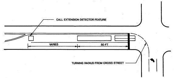
Figure 6-9. Extended Detection on Left-turn Lanes
Control of Arterial and Network Intersections
This section describes the data monitoring subsystem for traffic signal systems. System detectors are normally located in strategic locations within the system and usually require count and presence capability.
Volume and occupancy are the most commonly used variables in traffic control and are the most important factors in traffic-responsive plan selection and other real-time traffic-responsive algorithms. Volume proves to be the most easily obtained and accurate variable. Occupancy, as defined in Chapter 3, generally proves less accurate, since it can depend on vehicle profile and other factors. Measuring and detecting occupancy is extremely important, since it will continue to increase as intersections become saturated (Volume measures level off to a constant, proportional to green time divided by average vehicle headway.).
It has been observed that occupancies over twenty-five percent reliably indicate the onset of congestion (13). Accurate determinations of occupancy depend on the repeatability of the pickup and dropout characteristics of vehicles entering the detection zone and on variations in vehicle characteristics. An occupancy error is also introduced as a result of detector output being sampled by a communications unit or field microprocessor, rather than by continuous measurement. Therefore, occupancy measurements (in terms of percentage of error) tend to be more accurate at lower speeds. Chapter 3 describes several data-filtering and smoothing techniques relating to occupancy measurement.
A distinction should be made between system detectors and local actuation detectors. A local intersection detector connects directly to an actuated controller, whereas the system detector connects to the central computer or arterial master either directly or via the local controller.
Detector Locations for Conventional Traffic Systems
Data monitoring requirements for area wide traffic- responsive control depend on the control type.
Detector location for systems using the UTCS area control algorithm consists of a 3-step process that selects:
- Links,
- Longitudinal placement, and
- Lateral placement.
Link Selection is important, since cost increases in proportion with the number of detectorized links. A link is a section of roadway carrying a single direction of traffic flow between two signalized intersections. Links that approach the intersection of major arterials or the intersection of a major arterial with a moderately traveled arterial are usually selected for detector placement, as these links tend to dominate timing plan selection.
To implement timing plan selection by the UTCS algorithm, at least eight system detectors on different approaches in a single section are recommended. After 20 to 25 detector locations have been selected for a section, the value of information provided by additional detectors becomes marginal in terms of timing plan selection, but can be useful in providing additional resolution to the traffic operations engineer.
Longitudinal Placement for First Generation Control requires an accurate occupancy measurement to support the software.
Reference 14 recommends a distance of approximately 230 ft (70.1 m) from the upstream intersection stopline. Detectors should not be placed where standing queues from the downstream intersection typically extend. This distance depends on cycle length, split, and offset, but the following minimum distances are recommended:
- Urban grid areas: 200 to 250 ft (61 to 76.2 m)
- Suburban arterials: 300 to 350 ft (91.4 to 106.7 m)
The criteria based on typical queue size is considered more critical and should govern in the event of a conflict (14).
Another longitudinal-detector placement issue concerns traffic sinks and sources. Research indicates that a sink / source only minimally affects traffic in the critical lane when a facility operates as a sink; e.g., a parking garage during the morning peak. This results because vehicle turns into the sink usually occur from the curb lane, rather than the critical lane. Measurable effects on the critical lane were observed only during the evening peak, when the facility functions as a source.
Most vehicles exiting a source wait for a sufficient gap in their target lane before entering traffic. Therefore, a critical lane detector should be located at least 50 ft (15.2 m) downstream from the source, provided that this meets the downstream intersection criteria described earlier. In general, unless the source contributes more than 40 v/hr to the critical lane, its effects on link demand are insignificant.
Lateral Detector Placement. The lateral positioning of detectors refers to the lane or lanes in which they are to be installed. In general, detectors must be capable of measuring the highest lane volume at the intersection approach. The work of Henry, Smith, and Bruggerman indicates that at the midblock location, the lane designated as the critical lane did not change over the entire daytime period for approximately 65 percent of the cases (15). To identify the high volume lane on all links when not directly obvious, recommended steps include (14):
- Identify the intersection approach requiring detectorization,
- Conduct measurements for 20 signal cycles during the A.M., P.M., and midday periods at each intersection approach,
- Collect the data by positioning manual observers at the longitudinal detector position,
- Record volume data on a 5-minute basis, and
- Analyze the data by comparing the total volumes measured for the approach lanes.
In many cases, simple observation of an intersection will establish the high volume lane. These more detailed measurements will only prove necessary in areas where short-term observation of intersection operation does not permit critical lane selection.
Balke et al (16) discusses considerations for locating detectors for closed loop traffic control systems. The guidance is generally similar to that provided for systems based on the UTCS algorithm.
General Guidelines for Spotting Detectors. Previous sections describe:
- Selecting links to be detectorized,
- Appropriate longitudinal location, and
- Detector lane placement.
After completing a detectorization plan, the engineer should walk through each link to select final detector locations. This field check should also consider:
- Access to the controller cabinet,
- Special driveway problems,
- Pavement conditions and special situations, such as pavement construction joints, and
- Manhole locations.
- Bus stop locations
- Time of day parking restrictions
General guidelines concerning field location of individual loop detectors include (14):
- Locate a detector in the center of traffic flow, not necessarily in the center of the marked lane. Identify the center of traffic flow by oil markings or tire tracks on the pavement.
- Locate the detector in areas of stable traffic flow. Avoid sections of a link with excessive weaving or entering and exiting driveways.
- When a major driveway occurs within a link, locate the detector at least 50 ft (15.2 m) downstream from the driveway, provided the detector is at least 200 ft (61 m) upstream of the stopline.
- Traffic detectors should not be located within 10 ft (3 m) of any manhole, water valve, or other appurtenance located within the roadway. This distance permits sufficient clearance for work in the manhole without disturbance to the detector.
The final location of detectors for advanced traffic control strategies blends analytical procedures and engineering judgment. Not all links yield measurements within the algorithm's required accuracy. Short links, and links with poor lane discipline; typify those not amenable to accurate instrumentation.
1. Klein, L. "Traffic Detector Handbook." Federal Highway Administration Report, Washington, DC. To be published.
2. Klein, L.A. "Sensor Technologies and Data Requirements for ITS." Artech House, Boston, MA, 2001.
3. Tarnoff, P.J., A.M. Voorhees, and P.S. Parsonson. "Guidelines for Selecting Traffic Signal Control at Individual Intersections." Vol. II, National Cooperative Highway Research Program, American Association of State Highway and Transportation Officials, Federal Highway Administration, Washington, DC, July 19, 1979.
4. "NEMA Standards Publications for Traffic Control Systems. TS2-1992". National Electrical Manufacturers Association (NEMA).
5. Zegeer, C.V. "Effectiveness of Green Extension Systems at High-Speed Intersections." Research Report No. 472, Kentucky Department of Transportation, Bureau of Highways, Division of Research. Lexington, KY, May 1977.
6. Sackman, H., B. Monahan; P.S. Parsonson, and A.F. Trevino. "Vehicle Detector Placement for High-Speed Isolated Traffic-Actuated Intersection Control." Vol. 2: Manual of Theory and Practice, FHWA-RD-77-32, Federal Highway Administration, Washington, DC, May 1977.
7. Parsonson, P.S. et al. "Signalization of High-Speed, Isolated Intersections." Transportation Research Record 737, pp. 34-42, 1979.
8. Parsonson, P.S., R.A. Day, J.A. Gaulas, and G.W. Black. "Use of EC-DC Detector for Signalization of High-Speed Intersection." Transportation Research Record 737, pp. 17-23, 1979.
9. Kell, J.H., and I.J. Fullerton. "Manual of Traffic Signal Design." Institute of Transportation Engineers, Prentice-Hall, Inc. Englewood Cliffs, NJ, 1982.
10. Tarnoff, P.J., and P.S. Parsonson. "Guides for Selecting Traffic Signal Control at Individual Intersections." National Cooperative Highway Research Program Project 3-27 Research Results Digest 117, Transportation Research Board, Washington, DC, February 1980.
11. Wu, C.S., and L. Machemehl. "Detector Configuration and Location of Signalized Intersections." Report 259-1F, Center for Transportation and Research, University of Texas, March 1983.
12. "Design of Detection Loops Specifications." Section V, Illinois Department of Transportation, pp. 24-27.
13. "Computerized Signal Systems, Student Workbook." Prepared for the Federal Highway Administration, U.S. Department of Transportation, Washington, DC, June 1979.
14. Kay, J.L., R.D. Henry, and S.A. Smith. "Locating Detectors for Advanced Traffic Control Strategies Handbook." FHWA-RD-75-91, Federal Highway Administration, Washington, DC, 1975.
15. Henry, R.D., S.A. Smith, and J.M. Bruggerman. "Locating Detectors for Advanced Traffic Control Strategies." Technical Report, FHWA-RD-75-92, Federal Highway Administration, Washington, DC, September 1975.
16. Balke, K.N., S.R. Keithreddipalli, and C.L. Brehmer. "Guidelines for Implementing Traffic Responsive Mode in TXDOT Closed Loop Traffic Signal Systems." Texas Transportation Research Report 2929-3F, College Station, TX, August, 1997.
