Chapter 3. Telecommunications & the National ITS Architecture
Introduction
During the past 20 years, a number of technology based systems have evolved to support transportation operations, traffic management, traveler information, fleet management, and incident control. These include:
- Automated Traffic Signal Systems
- Commercial Vehicle Operations (CVO)
- Freeway Management
- Traveler Information
- Remote Weather Information Systems (RWIS)
- Incident Management
- Special Events
- Ramp Metering
- Electronic Toll Collection.
Automated traffic signal systems have been in use for over 50 years, while traveler information systems are still in the process of developing – especially since the FCC allocated 511 as a universal traveler information telephone number for the U.S. In fact, all systems are in a continuous evolutionary process because technologies supporting the systems are always changing. As a direct result of the change, telecommunications systems that support transportation operations are also evolving.
Chapter 3 will look at the relationship of the National ITS Architecture to the process of engineering and specifying communication links and services for a transportation management system. This chapter will also provide information on the developing standards within NTCIP and how they will impact on the design of communications systems supporting transportation.
Overview – The National ITS Architecture
The National ITS Architecture is a flexible framework for the interrelationship of operational transportation systems. Various telecommunications strategies can be used within the context of the National Architecture. These include urban and rural system deployments, for local and regional transportation management systems. Functionally, there are very few differences between urban and rural systems. Vehicle speed and volume detectors function the same in both situations, as do CCTV cameras, changeable message signs, and almost any other device used in transportation management systems. However, telecommunications strategies do vary based on location. A telecommunications architecture that supports urban deployments may not be suitable for a rural system. The key factors to consider when creating a design are distance of field devices to a control center, availability of electrical power resources, and availability of public telephone infrastructure.
The National ITS Architecture provides system developers with a detailed view of the relationships between travelers and associated transportation organizations. Each of the relationships has a communications requirement. Communications can be thought of as the glue that binds required operational functions. The National Architecture can be viewed in several different ways: Logical Relationship; Physical Relationship; Market Package Relationship; and Functional Relationship. The one constant in each type of relationship is communications. The Architecture makes no distinction in the type of communications systems that can be used. The system designer is free to use any telecommunications systems and devices that will support overall requirements.
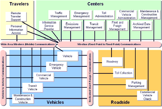
The National Architecture provides a diagram of the general relationships ("Sausage Diagram") listing four (4) generic types of telecommunications systems:
- Vehicle-to-Vehicle
- Dedicated Short Range Communications (DSRC)
- Wide Area Wireless
- Wireline
Wireline and Wireless are the two primary types of telecommunications architectures shown in the diagram, with Vehicle-to-Vehicle (VtV) and DSRC being two applications of wireless. There is no distinct requirement to use RF, Copper, or Fiber Optics as a transmission medium. Nor is there any suggestion as to the network topology: point-to-point, star, ring, mesh, etc.
Vehicle-to-Vehicle (VtV)
These are wireless systems and use radio frequencies (RF) as the medium. There are some systems that use light or sound for communication, but the systems used in traffic and transportation management are predominantly RF. VtV systems can use one, or a combination of radio systems for communication.
Mobile 2-Way Radio
Generally used between vehicles for wide area communication in a Private Land Mobile Radio Service (PLMRS) on frequencies set aside by the Federal Communications Commission (FCC) for that purpose. The system is used by DOT maintenance groups to facilitate operations between work crews and a central (or regional) dispatch center. Under the definition of the National Architecture, this is a wide-area mobile communication system. These same systems can also be used to coordinate joint operations between Police Departments and the DOT. These systems can also provide for an exchange of digital data information.
Cellular Telephone Service
Can be used for communication between the occupants of two (or more) vehicles. This system can be utilized to provide secure personalized travel and transportation information to individual travelers. The FCC requires that all wireless carriers provide location information when a request for emergency services is requested (the caller dials 9-1-1). The system may also be used to provide traffic management centers with general congestion information (not a requirement under FCC regulations).
DSRC
The sausage diagram shows this as a vehicle to roadside architecture, however, this is also considered as a very low power, very short range communication system between vehicles. DSRC generally refers to radio systems that operate on frequencies set aside by the FCC (in the US) between 5.8 and 5.9 GHz. However, toll collection and vehicle identifications systems currently operating in the 900 MHz range are considered – by the transportation industry – as DSRC. Automobile manufacturers have developed VtV systems using radar in the 35 GHz and 70 GHz frequency bands, and are looking at the possibility of using 5.8 GHz.
Dedicated Short Range Communication Systems (DSRC) are wireless systems used to communicate over distances of less than 1000 feet (300 meters). They can be used for vehicle-to-roadside (VtR ) or VtV. The systems are primarily deployed using RF, but can be deployed using infra-red (IR), or low power LASER as the communication medium. The National Architecture diagram shows DSRC in a relationship between the categories of Automotive Vehicles and Roadside Services:
These relationships are not fixed. Any vehicle using DSRC should be able to access a suite of services which include passing information between vehicles and the roadside. Standards for DSRC are being developed and tested by ASTM using IEEE 802.11a, as a basis. A major difference between the DSRC standard and 802.11a is the frequency range being used. DSRC will operate within a frequency spectrum set aside for this purpose, and requires licensing. 802.11a systems operate in a frequency spectrum that is set aside for general use and requires no license. Detailed information about DSRC is available at the following web site: http://www.leearmstrong.com/DSRC/DSRCHomeset.htm.
Wide Area Wireless Systems (WAWS)
WAWS are RF communication systems that can cover several square miles to thousands of square miles. They generally include Cellular and standard 2-Way Radio systems. Most of these systems are designed to provide full voice service and some data services. The National Architecture shows WAWS as providing VtV and vehicle to center communications (VtC). DOT Maintenance, Mass Transit, and Public Safety use WAWS as a tool for field to center communications. Additionally, Police and Fire agencies use these systems to enhance field unit communications.
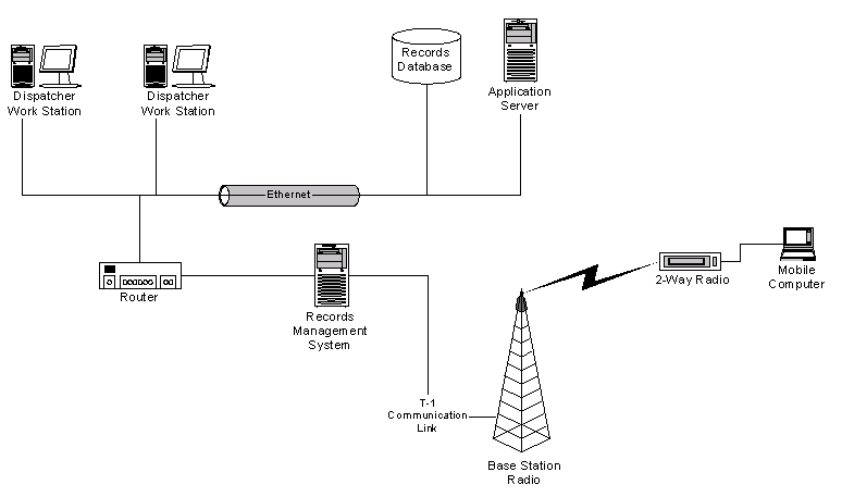
All WAWS have a similar architecture – a central base station that can communicate with mobile and handheld radios. The base station is a high powered transmitter and receiver combination placed in the center of the required coverage area. The base station utilizes an antenna placed at a relatively high (above ground) location (normally on top of a tower or building rooftop). Cellular systems are very similar in design except that there are many base stations interconnected by a wireline network designed to provide continuous service to callers using handheld radios (handsets). The overall system is interconnected to the PSTN to facilitate voice communication.
WAWS systems can also be used for field operational control of Freeway Management systems in rural settings. Oil and gas transmission companies use these types of systems for monitoring pipelines. These systems are called SCADA (system control and data acquisition). All incident and traffic flow detection systems are, in fact, SCADA systems in that they use various types of sensors to detect a change of state (vehicle speeds and lane occupancy) to alert TMC operators that a specific section of roadway may have a congested condition.
Wireline Systems
A generic reference to any type of system that uses a physical connection of copper wire or fiber optic cable as the communication link. Generally, wireline systems can be divided into three categories: Wide Area Network (WAN); Metropolitan Network (MAN); Local Area Network (LAN).
National ITS Architecture Flows & Telecommunications
This section will provide an examination of how market packages and flow models, as presented by the National ITS Architecture, can be used to create requirements for telecommunications systems and services. The NA is very large and has many components. The creators of the NA have developed "Market Packages" to help users work with the document. The Market Packages provide a graphical representation for easy visualization and can be a valuable tool in the design of a telecommunications system.
Market Packages
The market packages contained within the NA provide a good reference to how individual items (control center operators, roadway devices, data, and control systems) are positioned within a system, and their linked relationships. The system engineer must start at a very high level to produce an overview telecommunications architecture. As individual items within a market package are examined, their requirements will be added to the overall system. Modifications to the initial overview are made until a working telecommunications architecture is established. This is a "top-down" approach to help the engineer gain an understanding of the system that will be needed. In fact, the system is designed using a "bottoms-up" approach, because the system must provide communications services for every device in the market package. Let's take a look at a typical market package, and apply a telecommunications system.
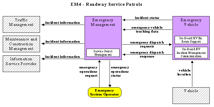
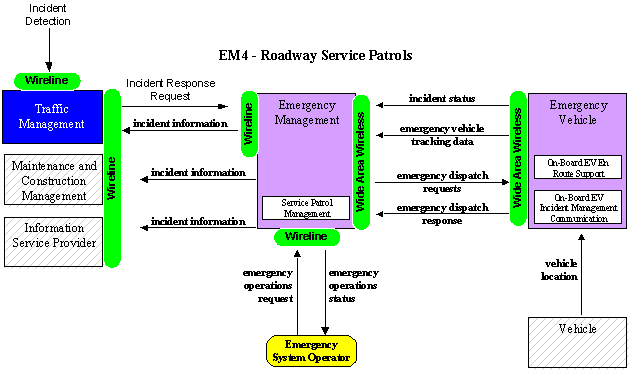
The Roadway Service Patrol Market Package (EM-4) describes a service that assists motorists with vehicle problems (flat tire, out of gas,) and is part of the incident clearance solution to help minimize congestion. Note that the selected market package is part of an overall "center-to-center" architecture. Ultimately, the solution for the situation described by this market package will have to become part of a larger communication system. In chapter Four, the process of breaking the overall communication system design problem into its basic elements is discussed. The graphic (8) shown is presented in the NA.
The above graphic represents only a small portion of the overall system that provides traffic management, incident detection, and incident response and clearance. The arrows indicate how information flows between the responsible agencies. These same arrows also provide an indication of the required communication links. Looking at the sausage diagram, it is easy to see that this system will utilize a combination of wireline and wide area wireless telecommunications systems. The NA does not specify the actual type of communications systems to be used. This is up to the individual developers of a system. The NA recognizes that the type of communication will be standard (and conform to FHWA requirements), but that each individual system will have different deployment variables. These include:
- Location – urban or rural
- Scope of services offered by the agency operating the TMC
- Budget – extensive or limited
- Regional or Local – system is "stand-alone" or part of a larger operation
- Coordination – level of cooperation between service providers
- Legacy.
Example Illustration
For purposes of illustration of the telecommunication system:
- The TMC is part of a regional operation with roadway service patrols offered by commercial contract organizations.
- The service patrols are dispatched by local Police Departments.
- The EM4 diagram shows several active boxes (Emergency Management, Emergency Vehicle, and Emergency System Operator).
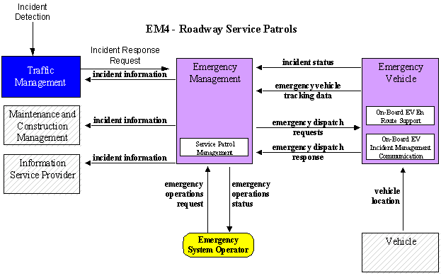
- The Traffic Management box is inactive, but we'll change it to active for this discussion.
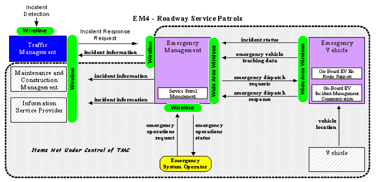
- Add several communication arrows not shown in this diagram. Take a second look at the EM4 diagram (Figure 3-4):
Notice that incident detection and incident response request flows have been added.
Next, assume the following:
- Traffic Management is a function of the DOT Transportation Management Center.
- Emergency Management is the responsibility of a County Emergency Management/ 911 Center.
- The dispatching is accomplished by a local Police Department (Emergency System Operator).
- The Emergency Response Vehicle is operated by a private contractor.
- Add the telecommunications sausage diagram elements (green) to complete the diagram (Figure 3-5):
The NA does not provide any details on telecommunication requirements or specifications. However, it does provide a good starting point via the Market Package Diagrams. Taking the diagrams and adding the telecommunications function is a good way to visualize the requirements. Program managers are provided a concept of the elements that must be detailed in the overall project. The importance of this is discussed in chapter Four. In the next section, we'll apply the telecommunication elements to the diagram.
Application of Telecommunications Using the National Architecture Flows
A good way to go from the market package concept to a telecommunication requirements document is to create a table based on the above diagram. The table will contain the "points-of-communication", and a brief description of needs. The developer of the table should also note that the Market Package describes information flows. These flows are not descriptive of the communication links, but can be used to help define the telecommunication links. The definition will include bandwidth requirements and the type of communication – voice or data or both. The following is an example of the table:
The items listed in the above table are the responsibility of the DOT, because the emergency management function is being provided by another agency. It is helpful for the system designer to have a complete understanding (for purposes of coordination) of the entire system, but it is only necessary to focus on the elements which must be provided by the DOT.
The TMC is responsible for creating the incident detection information, initiating a request to the EM and providing necessary information, plus coordination of support from the DOT. There is also the connection between the incoming incident detection information and the outgoing request for EM assistance to clear the incident. The system designer must provide for a communications link between the "in-house" TMC systems.
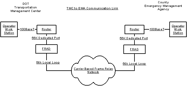
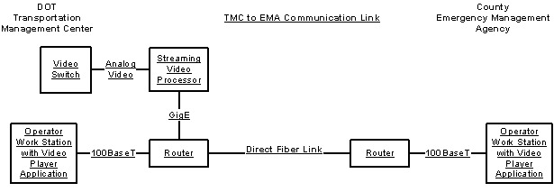
Notice that a dedicated communication port on the router is assigned to the link between the TMC and the EMA. This assures that the "incident response request" and "incident information" links are always available. Also, the use of a dedicated leased 56 Kbps digital circuit from a local carrier and the Frame Relay network assure secure transfer of information. The NA defines the requirements for each link as individual one way flows, but the telecommunications system design provides for a single bi-directional flow. The difference is that the NA is showing how information flows and the communication diagram is detailing a physical link. Also note that the above diagram represents one of several possible solutions. It essentially assumes that only text and database information are transferred between the TMC and the EMA. A system that provides for the transfer of "real-time" video from the TMC to the EMA would use a broadband communication solution.
In the diagram, the Carrier based solution has been replaced with a direct private fiber communication link. This could also be a link leased from a carrier.
Looking at the EM4 Market Packages, you will notice that a link is provided between the EMA and the Maintenance and Construction Management organizations. In a "real world" scenario, the link could be via the TMC. The NA is showing this link as a reminder that more than one transportation organization needs information. The overall design needs to account for each communication link.
Based on the NA, the Maintenance and Construction group receives information from the EMA, but does not send information back. We have to assume that construction and maintenance information is submitted to the EMA via another channel. This information is probably routine traveler information about lane and road closings and general repair work. For this case, the EM4 Market Package is a good model, but does not show all of the potential communication links. There may be a number of internal links that are not shown in the Market Packages. Do a thorough search of all of the requirements for communication.
Comparison of Rural and Urban Telecommunications Requirements Using the National Architecture Flows
In this section we will examine how the National Architecture works for both Rural and Urban telecommunication systems scenarios. The market packages and architecture flows are designed to remain unaffected by the location of the system. The variables are accounted for by making the market package and the architecture flows work in a particular situation – that is, meeting the needs of a rural or an urban/suburban location, and/or a local or regional system.
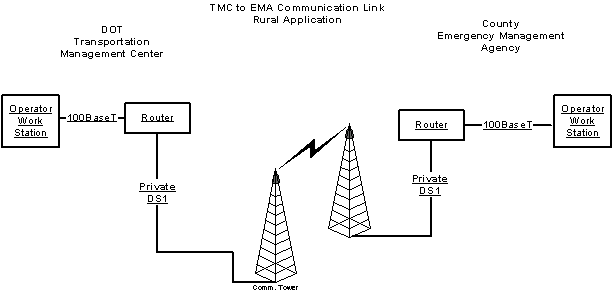
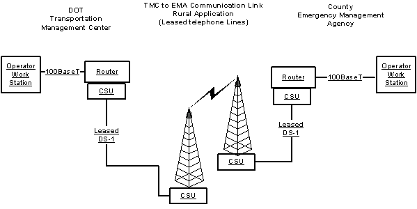
Using the EM4 Market Package, let's examine alternatives based on location. The Department of Transportation (for this scenario) is responsible for the Traffic Management function, and the County (for this scenario) is responsible for the Emergency Management function. The TMC and the County EMA are separated by several blocks or several miles. In an urban situation they are probably in separate buildings in the rural setting they may be in the same building, or separated by 20 miles. Let's look at the urban and rural separate building scenario and develop a communication link.
The diagram in the figures above are designed to facilitate the urban/suburban deployment. This single link will provide a physical path for the "incident response request" and the "incident information response" data flows. Please note that this information can be transferred in the form of voice or data. The final system requirements document will provide the details. For purposes of this illustration we will assume that the communication is a data transaction using a specific software application.
Rural Systems
The rural setting is characterized by a lack of available electrical power and telephone company infrastructure. This places a greater financial burden on the development of a telecommunications system. The rural communication links can use the same type of wireline system (as the urban example). However, a portion of the leased DS-1 link monthly fees are based on distance. In the urban system, the TMC and the EMA may only be separated by several city blocks. A rural situation could have the TMC and the EMA separated by 10 to 15 miles. The monthly cost of the leased line becomes a major consideration – a 56 KBps leased line may cost more in the rural setting than the DS-1 in the urban setting because leased telephone line services have a mileage based price component. Although the monthly fees are primarily based on bandwidth, a one mile DS-1 may have a lower overall cost than a 20 mile 56 Kbps leased line.
Several alternatives can be considered to help lower the overall cost of the communication link. Voice communication via a telephone is one way to keep costs down. A dial-up modem could be used for low bandwidth data communication. If a microwave system is available, a hybrid wireline-microwave system could be created. Many states have microwave backbones that can be accessed by multiple agencies. The key concept to understand is that the National Architecture flows are not affected by the telecommunications infrastructure. The following is an example of a hybrid block diagram.
The above diagram assumes that the TMC and EMA are located within 1000 feet of a microwave site. A privately constructed communications link to the tower sites would be very cost efficient. If the buildings are several miles from the sites, it may be more cost efficient to lease a DS-1 between the buildings and the tower sites. A comparison of communications systems used in rural and urban settings will show that rural systems are more expensive to construct. The variance in cost is accounted for on a distance basis. One of the primary engineering problems for telecommunications systems is that of overcoming distance. By comparison, rural systems must overcome significantly longer distances than urban systems. There are a number of other problems which must be overcome. Additional material about telecommunication problems associated with rural ITS deployments can be found in the addendum chapter. (9)
National Transportation Communication for Intelligent Transportation Systems Protocol (NTCIP)
The following statement is provided on the NTCIP introductory web page (10): "The NTCIP is a family of standards that provides both the rules for communicating (called protocols) and the vocabulary (called objects) necessary to allow electronic traffic control equipment from different manufacturers to operate with each other as a system. NTCIP standards reduce the need for reliance on specific equipment vendors and customized one-of-a-kind software. To assure both manufacturer and user community support, NTCIP is a joint product of the National Electronics Manufacturers Association (NEMA), the American Association of State Highway and Transportation Officials (AASHTO), and the Institute of Transportation Engineers (ITE)."
For telecommunication purposes, the NTCIP User Guide provides a further definition: "NTCIP is a family of communication standards for transmitting data and control information between microcomputer controlled devices used in Intelligent Transportation Systems". These standards are specific to transportation, and build upon existing (and developing) telecommunication standards and protocols.
A traffic signal control system using twisted pair (see chapter 2) communication links and an RS 232 interface before the implementation of NTCIP will continue to use the same wiring protocol after the implementation of NTCIP. This will also be true for an incident management system using CCTV transmitted via fiber optic cable. The physical interface for the transmission of data and their associated standards and protocols do not change.
Overhead is any information that is added to a communication transmission and is not part of the original message. This information is used to identify transmission origin and destination, assist with network management, look for transmission errors, etc. |
Implementing NTCIP as part of the telecommunications infrastructure requires careful calculation of bandwidth. NTCIP protocols add "overhead" to the communication process. Some systems that exist today can handle this added overhead without re-configuration. Others will require changes.
A traffic signal system that has 15 controllers sharing a single 9.6 Kbps multi-drop communication circuit may, (depending upon the specific NTCIP protocol) need to be reconfigured. The re-configuration may require the use of more bandwidth, or a reduction of the number of controllers on the circuit. The NTCIP User Guide provides a careful examination of the issues related to bandwidth calculation and the implementation of NTCIP. The NTCIP User Guide can be found at the following web address: http://www.ntcip.org/library/guide.asp
The material contained in this section was developed from information available from the National Transportation Communication ITS Protocol (NTCIP) web site. The reader is referred to http://www.ntcip.org for specific information and resources.
The National Transportation Communications for ITS Protocol (NTCIP) is a group of communications protocols developed for traffic and transportation systems. The transportation community has long needed a mechanism whereby interchangeability and interoperability for the various components of transportation systems could be achieved. It is for this reason that NTCIP is being widely embraced and is being specified for new system deployments.
NTCIP protocols allow for the interchange of devices of similar purpose and different manufacture to be placed in systems. The protocols allow for many different devices to share a common communication channel.
Interchangeability is defined as the capability to exchange devices of the same type (e.g., a signal controller from different vendors) without changing the software. Interoperability is defined as the capability to operate devices from different manufacturers, or different device types (e.g., signal controllers and dynamic message signs) on the same communication channel.
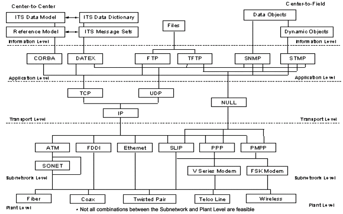
NTCIP is a suite of communications protocols and data definitions that have been designed to accommodate the diverse needs of various subsystems and user services of the National ITS Architecture. It is intended principally to handle these needs in two areas: communications between a management center and field devices, and communications between two or more management centers. Examples of the first application include transfer of command and configuration data between a transportation management center and field devices such as traffic signal controllers, dynamic message signs, environmental sensor stations, ramp meters, etc. Examples of the second application include transfer of data between multiple management centers within one agency, as well as transfer of data between management centers operated by different agencies.
NTCIP differs from past practice in defining communications protocols for management systems in that it is not a single communications protocol designed for one purpose. Rather it consists of a whole suite of protocols covering the spectrum from simple point-to-point command/response protocols to quite sophisticated object oriented techniques. This is because of the diversity of the applications into which NTCIP is being deployed, and the resulting diversity of application specific characteristics such as type and quantity of data to be transferred, criticality of data transfer times, acceptable cost of communications infrastructure, criticality of data security and integrity issues, to name a few. Insofar as data definitions are concerned, NTCIP does not completely define the functionality of the central or field devices to which it applies. It only specifies the data objects to be transferred and limited functionality directly related to these objects. For example, NTCIP does not define the details of how a traffic controller operates, e.g., it does not define that a green must be terminated by a yellow and that a red must be displayed after a yellow. However, it precisely defines the data that may be communicated between traffic controllers and traffic management centers, and thereby defines the aspects of functionality (e.g., it requires that the length of the yellow clearance interval must be as indicated by the phase Yellow Change object).
NTCIP standards and protocols are not designed to replace the general suite of communication standards and protocols developed by other standards organizations (e.g.: IEEE; ASHTO; etc.). In fact, it incorporates many of those standards.
The introduction to this chapter indicated that the use of protocols adds the "cost of bandwidth". The primary rule that needs to be followed in the design of a communication system is – "nothing is free!" Every communication protocol adds to the total amount of data being transported. The requirement for additional bandwidth to accommodate "overhead" protocols should not be considered in negative light. But, it must be considered!
"Overhead" is anything that adds to the communication requirement. Any protocol for network management, any information that identifies a device, any information that is used for command and control, and routing information is considered as overhead. If the information is not part of the message – it's overhead! Note: The actual amount of overhead required by the use of NTCIP, or any other OSI layer support is dependant upon the actual configuration of the NTCIP, or OSI Model, layer protocol.
NTCIP is used for device management and systems message management. The following tables provide examples of NTCIP protocols:
As of the date of this handbook, individual NTCIP system packages are still under development. The reader should check at the web site for the latest information.
Conclusion
From a telecommunications perspective, neither the National ITS Architecture, nor NTCIP provides answers to design problems. NTCIP is a recommended set of communication protocols based on existing (telecommunication) standards. The National ITS Architecture provides significant detail on communication flows, but, does not provide a design of the telecommunications system. The developers of the architecture understood that the design of a communication system would be unique for each ITS system.
8. http://itsarch.iteris.com/itsarch/html/mp/gatms08.htm
9. Written Testimony of Stephen Albert, Director Western Transportation Institute, Montana State University to United States Senate Committee on Environment and Public Works Subcommittee on Transportation, Infrastructure and Nuclear Safety.
