Chapter 8. Construction
Introduction
Chapter Two presented the term media to describe the physical layer of a communication system that is used to convey information between two or more points. This chapter presents guidelines that should be used in the handling of the media during construction. The items described in this chapter are typically the responsibility of a general contractor, however, it is important for project managers and consultants to have a good knowledge of the construction process. General design and construction practices are the same as those associated with almost any civil works project. Conduit and direct-bury cable projects need to be designed using cable and conduit manufacturer recommendations for bending radii, and cover depth specifications. Towers and poles supporting radio antennas need to be designed using manufacturer recommended mounting and support guidelines.
Many of the presented guidelines have been developed by manufacturers wanting to make certain that customers are satisfied with their products. Other guidelines have been developed based on observation of common mistakes made by construction contractors. The most important recommendation that can be made is to carefully monitor the construction process. Don't let contractors take "shortcuts". Make the manufacturer construction and media handling guidelines part of the project specifications. There may be good reason to not follow the recommendations (or the specification), and the contractors should be required to explain the need to deviate. Most requests for this type of action will be in the form of a "path" re-alignment. Treat the request as you would for any other highway construction project.
The physical design of the media path should conform to national and local construction design codes. Most municipalities issue construction permits. Many have specific codes relating to the locations of conduit or radio towers.
For very large projects, hire an independent construction management firm to observe the testing and construction process. Train in-house personnel to observe smaller projects. Require construction contractors to follow manufacturer recommendations for installation of their products.
Much of this chapter is devoted to the care and installation of fiber optic cable. Copper (twisted pair, coaxial, and antenna cable) transmission media cable require similar care and testing during installation.
Handling and Installation of Fiber Optic (and Copper) Communications Cable
Most ITS, Traffic, FMS systems use fiber optic, or copper cable as the primary communications transport medium. Use of the recommended procedures during installation can save a substantial amount of money. Most media problems occur because of a lack of care during installation. This section provides guidelines for the installation of "outside plant" communication cable. Each cable manufacturer will provide specific information related to the product they provide about care and handling during installation.
Following is a list of recommendations for the handling and installation of fiber optic communications cable. These same general procedures can also be followed when installing coaxial or twisted pair cable. The general procedures and requirements apply for all fiber optic communications cable whether installed aerially on communications utility poles, or in underground conduit, or structure attached conduit, or inner-duct placed in conduit, or direct burial.
- Receiving and inspecting the cable
- Unloading, moving and storing the cable
- Testing cable on reels
- Documentation and record maintenance
- Cable Installation
Receiving and Inspecting Fiber Optic Cable
Let your cable manufacturer or distributor customer service representative know of any special packaging or delivery requirements (no shipping dock available, call before delivery, etc.). Put this information in the specifications so that contractors will be aware of these requirements. Make certain that personnel with test equipment are available. It is important to test damaged (or suspect) cable reels before accepting delivery – request 24 hours notice.
When the shipment arrives, make sure the cable types and quantities match the bill of lading. Inspect every reel and pallet of material for damage as it is unloaded. Suspect cable should be set aside for a more detailed inspection before the shipping documents are signed. The delivery persons may be on a tight schedule, but they aren't paying for the cable!
Notify the general contractor and the manufacturer/distributor that there are damaged cable reels before signing for the cable. Follow-up the telephone call with a written notice via e-mail or fax.
- Receipt of the cable does not imply acceptance!
- You may be pressured (by the distributor) to accept the cable by being told that you will have to wait 18 months for new cable.
- Remind the person applying the pressure that they won't get paid until the order is complete.
- Accept a 30 day delay in return for having a fully functional system. The delay will cost less than replacing damaged cable.
Some additional points to consider:
- Reels of optical fiber cables are shipped on their rolling edges not stacked flat on their sides. Make sure you note the orientation and condition of the reel in your inspection.
- If any cable damage is visible or suspected and if it is decided to accept the shipment, note the damage and the reel number on ALL copies of the bill of lading.
- If the damage is too extensive to accept the shipment, advise the carrier's driver that the shipment is being refused because of the damage. Immediately notify the cable manufacturer/distributor, Customer Service Department so that arrangements can be made for a replacement shipment.
- Cable performance test results taken at point of manufacture and reel loading are provided with each reel. Compare them to your own tests using the methods outlined in the cable testing section.
Unloading, Moving, and Storing Cable
When unloading the cable reels from the delivery truck, exercising care is important. The reels may look like two wheels on an axle, but they should never be rolled off the back-end of the truck. The reels are heavy and may contain from 5,000 to 15,000 meters of cable. Following are guidelines for unloading, moving and storing of communication cable reels:
- Optical fiber cable reels are typically very heavy and, therefore, they must be loaded and unloaded using a crane, special lift truck or forklift.
- Forklifts must pick the reel up with the flat side of the reel facing the forklift operator.
- Extend the forks under the entire reel.
- Keep all reels upright on their rolling edges and never lay them flat or stack them. Optical fiber cable reels are always stored on the rolling edge
- All reels are marked with an arrow indicating the direction in which the reel must be rolled. Roll only in the indicated direction.
- DO NOT drop reels off the back of the truck onto a stack of tires, onto the ground or any other surface. The impact may injure personnel and will damage the cable.
- The reel is labeled with handling directions. Consult these directions if you have any doubt about handling the reel.
- To prevent reel deterioration during long term storage, store optical fiber cable in a manner that protects the reel from the weather.
Testing the Cables
Manufacturers test the cable for continuity at the factory once it has been loaded onto the reel. This is your assurance that there are no breaks in any of the fiber (or copper) strands that make up the cable. The results are published and added to tags on the cable reel and to the paperwork that accompanies each cable reel. Do not accept any cable reels that lack the testing documentation. There are five phases associated with testing of fiber optic cable starting at the point of manufacture:
- Factory cable reel testing and documentation,
- Visual inspection at the delivery site for shipping damage, and possible reel test,
- Pre-installation testing, which occurs when the cable is delivered to the job site, and before it is installed,
- Installation testing, which occurs after the cable is pulled through the conduit (or mounted on poles) and at every splice point,
- Final acceptance testing, which occurs just prior to activation.
Why is testing so important, and why so many tests? Each test phase occurs at a responsibility hand-off.
- Factory to shipping company
- Shipping company to general contractor (or DOT)
- General Contractor to installation (path construction) company
- Installation Company to splicing contractor
- Splicing Contractor to end-user
Each entity will claim that the cable was in good condition when it made delivery of the product or service. Testing at each stage assures that liability for damage can be placed with the appropriate company. A significant portion of the cost of constructing the fiber optic cable system is in the final installation (cable pull, splicing and quality testing) of the cable. Imagine having to replace 15,000 feet of cable because of damage sustained during the pulling. Knowing that the installation contractor is responsible will save a lot of time and finger pointing.
Following is a list of testing guidelines:
- Testing reels of optical fiber cables at delivery is not required (most manufacturers suggest that this be done to ensure that damage did not occur during shipping), however, testing prior to, and after construction is essential to identify any cable performance degradation caused during installation. Testing prior to installation provides a baseline of performance.
- Pre-installation Testing – This typically consists of an OTDR (Optical Time Domain Reflectometer) test performed at 1550 nm. All optical fiber cables must be bi-directionally OTDR-tested prior to shipment and the test report attached to the reel. Bi-directional testing is important to verify results and to make certain that no potential problems were missed. Remember, the data can flow in two directions on the fiber strand. Test to make certain that it will.
- A pre-installation test will verify the characteristics of the cable and check for any shipping damage. The tests must be jointly conducted by the system operator and the construction contractor in order to preclude future difficulties should a cable be damaged during construction.
- Installation Testing – Cable should be tested once it has been placed in the conduit, or on the poles, and prior to splicing to make sure that there has been no installation damage. Installation testing is usually done with an OTDR.
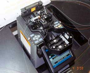
- Splice testing is done after each splice to ensure that a clean, low-loss connection was made. OTDR, local injection detection and profile alignment can be used alone or in combination for splice testing.
- Post Installation – Final Acceptance Testing – The usual post installation testing method is to perform end-to-end OTDR testing from both directions. The results should be compared to the pre-installation test. It is highly recommended that an ongoing testing program be established after the system is powered up.
- It is important that technicians testing the fiber use the same brand and model of test equipment and the same testing profile. Use of different test equipment and profiles will result in confusion and inconsistent test results.
- Make certain that someone on your staff (or the communication engineering consultant) is able to understand the test results to verify that all specifications have been met.
Documentation and Record Maintenance
"The best defense is a good offense", is a phrase that should be applied to the construction of a communication cable system. Optical fiber installation involves multiple fibers in a cable that may be very long and have many splices and connections. If cable is damaged during installation and not detected by on-going field testing, the replacement costs can be extremely high. It is recommended that the following records be maintained and kept current on a daily basis:
- schematic drawings – to include "as-built" information for street maps records
- splice loss data
- end-to-end optical loss measurements
- end-to-end OTDR signature traces
- end-to-end power meter tests
The documentation is needed to provide historical references for maintenance and, emergency restoration. By maintaining this data, the system operator is assured of a prompt repair response by the quick identification of the location of any problem that may occur within a cable. Data collection starts with the delivery of the fiber cable, continues through construction and for the life of the system as new devices are added.
Following is a list of data that should be collected for the permanent record:
- Calculated data obtained from cable reel data sheets and splicing logs.
- Measured data, such as OTDR data, is obtained from end-to-end cable testing.
- Total amount of cable pulled between splice points – including slack coil loops
- Placement and use of pull boxes and cable splice boxes
- Accurate street maps showing the location of fiber cable and all accessory items
- Accurate location information of any repairs
- Maps that show where other utilities cross the fiber cable, or are in close (parallel) proximity to the cable
- A record of all communication devices connected to the fiber cable
- Where conduit (or the cable trench) is shared – list the other users
- Any other information that might be needed to support changes or emergency repairs.
General Cable, Installation, and Design Guidelines
The following guidelines are presented to assist in the general design, construction and installation of fiber optic cable systems. Many of these guidelines can also be used for other types of communication cable.
Cable Pull-box/Splice-box Placement
- Every street (up to 50 feet wide) crossing – one (1) box located within 10 linear feet of the crossing, unless a traffic device (signal, DMS, video detector, etc.) is located near (within 50 linear feet) of the crossing.
- Every freeway, railroad, or bridge crossing – two (2) boxes located (one each) at the terminal points of the crossing.
- All mid-span splices must be placed in a splice box and secured in an appropriate cable tray.
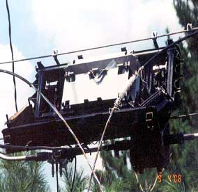
- All splice boxes used for aerial cable installations should be mounted on a convenient utility pole. If no space exists on the pole, then a suitable in-ground splice/pull box must be installed near the utility pole. All cable leaving the aerial installation must be installed in conduit.
- All splice points must contain sufficient slack (50 foot minimum) to allow for future addition of communication devices, cable and splice repairs, or additional runs of "drop" cable. This would be especially true if the cable is located within a freeway right-of-way.
- All splice boxes must be properly grounded according to NEC. EIA/TIA and Bellcor (Telcordia) standards.
- Aerial mounted splice boxes should only be used for temporary repairs – in fact, many carriers use them for permanent repairs.
- Mid-span cable meets (points where ends of cable reels meet) must be fusion-spliced and enclosed in a splice box. Never use a mechanical splice to connect cable reel ends.
Cable Installation and Pulling Guidelines
Pulling Tension:
- Each manufacturer has specific instructions and specifications for the amount of tension that may be used when pulling a fiber optic cable. The contractor is required to follow the cable manufacturer's specifications and recommended installation procedures.
- Kellems or crimp-on grips are used to pull the optical fiber cable. Use the correct-sized grip for the cable being pulled.
- If Aramid® yarn is part of the cable structure; tie it to the grip to further distribute the pulling force. NEVER EXCEED the maximum pulling tension.
- Excessive pulling force will cause the cable to permanently elongate. Elongation may cause the optical fiber to fail by fracturing.
- Good construction techniques and proper tension monitoring equipment are essential.
- When installing aerial cable place enough cable blocks along the route to keep cable sag to a minimum. Excessive sagging will increase pulling tension.
- When pulling, do not let the cable ride over the reel flange as it may scuff or tear the jacket.
- Tail loading is the tension in the cable caused by the mass of the cable on the reel and reel brakes. Tail loading can be minimized by using little to no braking during the pay-off of the cable from the reel – at times, no braking is preferred.
- Dynamometers must be used to measure the dynamic tension in the cable.
- Break-away swivels should be used in conjunction with dynamometers to ensure that the maximum pulling tension is not exceeded.
Cable Bending Radius Guidelines:
- Cables are often routed around corners during cable placement. NEVER EXCEED the minimum bending radius. "Over" bent cable may deform and damage the fiber inside.
- Bending radius for optical fiber cable is given as loaded and unloaded.
- Loaded means that the cable is under pulling tension and is being bent simultaneously.
- Unloaded means that the cable is under no tension or up to a residual tension of around 25% of its maximum pulling tension. The unloaded bending radius is also the radius allowed for storage purposes.
- Do not exceed minimum bend radii or the maximum pulling tension.
- Follow all pulling tension and minimum bending radii instructions and specifications issued by the cable manufacturer.
- In general, plan the cable path to eliminate as many curves and bends as possible. Curves and bends add to the attenuation of the fiber optic signal.
Pulling Strategy Guidelines:
- Fiber optic cables can be ordered in lengths on a single cable reel and can be installed in one continuous run. However, even a typical installation of 3–5 miles/5–8.0 km offers installation challenges because of the accumulation in pulling tension along such a long route. This tension can be eased by using intermediate assist devices like a series of mechanical winches or capstan drives connected to a master controller. However, if these devices are unavailable, a midpoint cable pull must be used for installing long lengths of optical fiber cable.
- The cable is installed from a midpoint to the endpoints.
- Make certain that all conduits are clear of obstructions. Use a water based lubricant to reduce outer sheath corrosion.
- Existing conduit may need repairs – inspect carefully.
- When installing aerial cable, make certain that the path is clear of tree limbs.
General Cable Construction Guidelines
Cable is generally installed using one of three methods: aerial, direct burial, or in conduit. This section provides some general guidelines for using these construction methods. The methods are listed in order of cost to construct. Aerial is generally considered lowest cost with conduit placement being the highest cost.
Aerial Construction
Aerial cable is typically strung from pole-to-pole, or from building-to-pole. Two types of cable are available: self-supporting or lashed. The self-supporting cable is designed with either a heavy duty central strength member, or in a figure eight configuration that has an external strength member that can be clamped. Lashed cable is similar to cable that can be direct buried and requires a "messenger support wire" to which the cable is affixed.
When using aerial cable, the engineer must provide sufficient supporting utility poles in the route to minimize the effect of cable sag. This is caused by external forces such as wind, ice and extreme temperature changes added to the weight of the cable. Manufacturers provide specifications to assist with cable route design and planning.
FHWA has produced the "Design Guide for Fiber Optic Installation on Freeway Right-of-Way", publication # FHWA-OP-02-069. Consult this document for additional information and guidance. |
Here are some general guidelines:
- Use of tight buffered cable is not recommended for aerial installation
- Use a cable with a UV protected sheath to minimize effects from sunlight
- Use a metallic armored cable to minimize damage from squirrels and birds.
- Always follow the manufacturer recommendations for self-supporting cable installations. Consult the manufacturer for additional information when varying from recommendations.
- Allow for storage of sufficient slack loops to account for problems associated with cable breaks and pole damage from severe weather and vehicular accidents.
Table 8-1 is excerpted from a Corning Cable product brochure for self supporting fiber optic cable. Please consult the cable manufacturer's documentation for recommendations about installation under severe weather loading conditions such as high wind or severe ice and snow accumulation areas.
Notice that as the number of fiber strands contained in the cable increase, the distance between utility poles decreases. The same is true for loading factors.
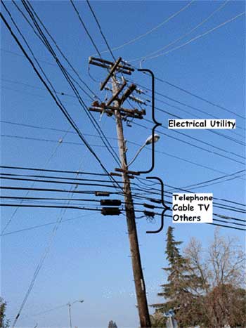
Construction of aerial cable involving the use of existing utility poles, requires access permits from the owner of the pole. In most cases, the owner is the local electrical power utility, but some poles are owned by telephone companies. Utility poles are marked with identification tags.
The electrical power lines are always placed at the top of the pole. Telephone carriers are placed at the next lower level with about 10 feet of vertical separation from the electrical lines. Other users are located above the telephone lines, but with at least 10 feet of vertical separation from the electrical utility. The lowest set of lines must be placed at least 15 feet above grade. If there is not enough room to accommodate all valid users, it is necessary to raise the height of the pole. The last user is responsible for paying the cost of installing the extension (or taller pole) and moving all users to their appropriate position. Using existing utility poles can be very expensive.
Direct Burial Construction
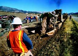
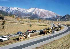
Cable can be buried directly in soil using one of two general construction methods: open trench construction, or cable plow. In both instances, a cable rated for direct burial should be used. These cables are designed with a metallic armor sheath to prevent damage from rodents that may try to chew through the cable. The direct burial method is especially useful in rural and suburban locations. The non-paved portion of a rural road or highway right-of-way is a good candidate for this construction method. The route must be carefully planned taking care to avoid other buried utilities (water, electrical, telephone, gas, etc.) and meeting environmental requirements.
Using the open trench construction method, a backhoe is used to dig a 36 inch deep trench. The trench is backfilled with an appropriate material to prevent cable bends due to settlement. The trench is then filled to a level of 24 inches. A yellow warning tape is then laid in the trench before completing the fill process to terrain level. The 36 inch depth is an average. The cable should always be buried below the frost line. The actual depth of the cable may vary based on road crossings, or drainage ditch (drainage lines) crossings. The object is to keep the cable out of harm's way.
A second direct bury construction method uses a plow to open the earth, lay the cable and then cover. This is an economical and efficient construction method. However, no warning tape is installed.
Use of these methods does not eliminate the need to consider placement of slack cable and access handholes. There will always be a need to add communication devices and access nodes to a system.
Direct buried cable is always identified at the road level using orange marker poles. The poles have information indicating that communication cable is buried below together with contact information in case of damage to the cable. Markers should be place about every 1000 feet, plus on either side of a road crossing, drive way crossing and bridge crossing.
A variant of the direct bury cable construction method is direct bury of flexible conduit. If plans call for installation of additional fiber cables (in the same route) within a few years, the burial of flexible tube conduit with the initial cable provides significant savings over re-opening a trench. "Level 3" (a communication carrier) used this construction method to provide additional resources for the future. When "Level 3" needs to install additional fiber cable in their route, the flexible tube conduit can be used to minimize construction costs. This method also reduces traffic congestion due to construction.
Conduit Construction
Placing cable in conduit is the most expensive solution for constructing a fiber optic cable route. Starting from scratch requires a significant amount of planning, especially in urban areas where most conduit is used. All utilities in (or near) the proposed construction path must be located and marked. The path may have to be realigned to avoid some of the utilities, or a proposal developed to temporarily interrupt service and then repair the damaged utility lines. Environmental issues must be addressed. Where construction is proposed for existing streets or roads, repair and restoration costs must be considered. Maintenance and protection of vehicular and pedestrian traffic must be implemented.
The conduit structure must be designed to meet bending radius requirements of the communication cable. The inside conduit diameter should be at least 25% larger than the outside diameter of the cable. This helps to prevent cable drag when pulling through the conduit.
Cable installed in conduit should be rated for immersion in water. All in-ground conduit eventually contains some water. Cables designed for this purpose are constructed with a sealant that prevents water from penetrating the fiber (or copper) transmission media.
If the conduit is buried at a depth of greater than three feet, it may be necessary to dig a trench that is wide enough to allow space for construction personnel. Trenching at a depth of more than six feet, will require "shoring" walls (see local construction codes for specific requirements) to prevent collapse and injury to construction personnel.
Most conduit used for telecommunications cable projects is high density polyethylene (HDPE). The ASTM has developed a recommended standard, ASTM F2160, "Standard Specification for Solid Wall High Density Polyethylene (HDPE) Conduit Based on Controlled Outside Diameter (OD)". This standard was developed to assure that conduit from different manufacturers could be used with assurance that the inside and outside diameters of conduit pipe and the thickness of the conduit wall would match.
Some DOT's may require the use of steel conduit for bridge crossings or other types of construction. Using appropriate couplings, steel and HDPE can be mixed. HDPE is lighter in weight and easier to handle than steel, however, under certain loading circumstances it may not be as rigid.
Wireless Systems Construction
Wireless media are used to support communication links between devices and the TCC. This is often viewed as a low cost alternative to the installation of communication cable. Many departments are using spread spectrum radio in the 900 MHz and 2.4 GHz range.
This section will focus on mounting of radio antennas and transmission line for "line-of-sight" (also called microwave) radio systems. These are the systems commonly used for traffic control and freeway management.
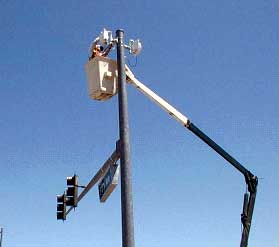
Spread Spectrum Radio, DSRC, and the emerging 802.16 Wi-Max, or WLAN systems all require line-of-sight design. The design and construction of towers and poles is completed within standard civil engineering practices and local codes. This also holds true for building mounted antenna supporting structures.
Planning for Wireless Systems
System planning is critical to the successful installation, operation and proper performance of any communication system, wireless systems are no exception, and this is especially true for line-of-sight (microwave) wireless. Unless your proposed microwave link will be operating over a very long path, you should be able to confirm whether a visible line-of-sight path exists between the two proposed antenna sites. This is only a first-step process, and is often accomplished by using a combination of strobe lights, mirrors (which reflect the sun), binoculars and spotting scopes. Being able to see one site from the other will not guarantee that the visible path is appropriate for a microwave signal, but at least you who know that the possibility of such a path exists.
"Line-of-sight" is a term used in radio system design to describe a condition in which radio device antennas can actually see each other. High frequency radios, such as those used in Spread Spectrum Radio require line-of-sight between antennas. |
In many instances there may be obstacles to overcome such as buildings, trees, small hills and elevated roads, and it may not be possible to confirm that line-of-sight exists without additional aid. Keep in mind that even a "perfectly clear" visual path may not actually be so. As an example, small branches of deciduous trees, barren in the winter, may not be visible until spring or summer when growth appears. Even the skeleton of a new building may not be visible until the sides go up! Establishing line-of-sight for traffic signal systems should be easy to accomplish because of the short distances involved (a few blocks).
When establishing line-of-sight, it is extremely important to plan for the future. In urban areas, new building construction may result in total path obstruction. In areas where construction is not anticipated, the rapid growth of trees or foliage may severely affect the path over time. While a number of software products are available for assisting with path work, combining a topographical mapping of the path with a subsequent path walk or drive is often an excellent way to start the line-of-sight confirmation process.
Assuming an appropriate line-of-sight path from radio site to radio site can be established, both the feasibility and viability of a point-to-point microwave radio link will be dependent upon the gains, losses and receiver sensitivity corresponding with the system. Gains are associated with the transmitter power output of the radio, and the gains of both the transmitting and receiving antennas. Losses are associated with the cabling between the radios and their respective antennas, and with the path between the antennas. Other losses can also occur if the path is partially obstructed, or if path reflections cancel a portion of the normal receive signal. Manufacturers will state respective RF power output and gain for each of their products.
Radio transmitters are described in terms of power output expressed in watts. The power output may also be expressed in terms of decibels of gain (dB). Radio receivers are rated in terms of sensitivity (ability to receive a minimal signal). The rating is listed in terms of milliwatts (mW), or decibels of gain (dB). Antenna cable is rated in terms of signal loss per foot and expressed as dB of loss per foot. The antenna is rated in terms of gain (dB). There are a number of software programs that will calculate path loss by frequency and use the specifications of the system hardware to help determine the overall system feasibility.
One of the first items to consider for any microwave path is the actual distance from antenna to antenna. The further a microwave signal must travel, the greater the signal loss. This form of attenuation is termed free space loss (FSL). Assuming an unobstructed path, only two variables need to be considered in FSL calculations:
- The frequency of the microwave signal – numerically higher frequencies require more power to cover a given distance.
- The actual path distance – the greater the distance the greater the signal loss.
A signal transmitted at a frequency of 6 GHz will have more available power than a signal transmitted at 11 GHz. For example, a microwave system at 6 GHz can expect to cover about 25 miles between communication points. The same system using a frequency of 11 GHz will only cover about 10 miles.
When RF energy is transmitted from a parabolic antenna, the energy spreads outward, much like the beam from a flashlight. This microwave beam can be influenced by the terrain between the antennas, as well as by objects in or along the path. When the centerline of a beam from one antenna to another antenna just grazes an obstacle along the path, some level of signal loss will occur due to diffraction. The amount of signal loss can vary dramatically, influenced by the physical characteristics and the distance of the object from the antenna.
A microwave beam can also be reflected by water or relatively smooth terrain, very much in the same way a light beam can be reflected from a mirror. Again, since the wavelength of a microwave beam is much longer than that of a visible light beam, the criteria for defining "smooth terrain" is quite different between the two. While a light beam may not reflect well off of an asphalt road, a dirt field, a billboard, or the side of a building, to a microwave beam these can all be highly reflective surfaces. Even gently rolling country can prove to be a good reflector.
A microwave beam arriving at an antenna could effectively be canceled by its own "mid-path" reflection, causing tremendous signal loss. Long microwave paths can also be affected by atmospheric refraction, the result of variations in the dielectric constant of the atmosphere.
For relatively short 2.4GHz microwave paths, only reflection points and obstructions are usually of real concern. The effects of atmosphere and earth curvature will not usually come into play, so the engineering of these paths is quite straightforward. For long or unusual paths, however, all aspects of path engineering must be considered.
Interference Issues – Spread spectrum microwave radio systems are among the most interference tolerant communication networks in use today. Spread spectrum signals are very difficult to detect and, by their nature, are highly resistant to jamming and interference. As more and more signals are transmitted, the "noise level" in the band increases accordingly. Once the noise reaches an identified level, communication in the band is effectively negated.
In the U.S., the 2.4GHz band is license free, making it very difficult to know whether or not another spread spectrum radio is operating in a manner which could possibly interfere with one's own link. While these links are usually able to spread narrow band interference, other spread spectrum signals in the 2.4 GHz band could possibly interfere if they are of the proper frequency and amplitude. It is extremely difficult to predict the effect of an interfering signal unless specific information is known about the interferer. In general, other spread spectrum signals in the 2.4 GHz band tend to raise the band's noise floor. For this reason, even when working with paths which are very short and not subject to any sort of fading condition, a fade margin of 15 dB or greater should always be maintained for the path.
A Word About Antennas
All RF systems have an antenna (or several in an array). The transponder used in a vehicle for toll collection has an antenna. The fact that it can't be seen doesn't mean that it isn't present. The antenna is built in-to the package. A cost comparison of all the elements that make up a radio system would show the antenna as the lowest cost piece. However, most of the problems that a radio system may have can be traced to either improper installation, or improper selection, of the antenna. Follow the recommendations listed below for proper installation.
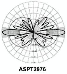
All antennas have similar characteristics. They are designed with vertical and horizontal polarity. The manipulation of these characteristics creates a specific antenna coverage pattern. Some antennas are designed to provide a circular pattern referred to as omni-directional. Others have an elliptical pattern referred to as uni-directional. Antenna manufacturers will routinely provide the horizontal plane pattern as part of their product literature. An engineer can request a copy of the vertical pattern if necessary. The antenna pattern display is for an Antenna Specialists, Inc., 2.4 GHz Spread Spectrum radio system. The antenna projects two highly directional lobes. When setting up a radio system, it is critical that the installers match the pattern lobes to the system design. If the direction of the lobes is off by just a few degrees, that may cause the system to have a marginal performance.
Guidelines for Handling & Installation of Wireless Antenna and Transmission Cable
RF Transmission cable should be treated with the same care as fiber optic communication cable. This is important. To prevent interference with other radio systems on the tower the transmission cable is constructed with an internal shield of copper or copper foil. If this shield is broken, your system could cause interference with other systems at the site. Also, once the shield is cracked, your system is subject to interference. Some radio transmission cable uses a hollow copper tube to act as a "wave guide". If the hollow tube becomes damaged your system might not function properly. The following guidelines apply:
- All cable should be inspected and tested when received.
- All test results should be compared with factory pre-shipping tests.
- Inspect the cable nomenclature to make certain that you received the correct product.
- Notify the supplier (or manufacturer) of all discrepancies as quickly as possible.
- Follow the manufacturer recommendations for installation
- Cover all exposed cable ends to make certain that moisture does not penetrate the cable assembly.
Mounting cable on a pole or tower structure requires the use of qualified personnel, test equipment, and care to prevent damage to the transmission line:
- Use a hoist line that supports the total weight of the cable – refer to manufacturer specifications
- Use pulleys at both the top and bottom of the pole (or tower) to guide the hoist line.
- Support the cable reel on an axle so that the cable can be freely pulled from the reel. Have a crew member control the rotation of the reel.
- Short lengths of cable coiled and tied. Uncoil the cable on the ground away from the pole before hoisting.
- After raising the cable to the top of the pole, anchor it to the support structure from the top down.
- Never anchor the cable to an electrical (or lighting) conduit.
- The top and bottom of the cable attached to the pole should be electrically grounded to the pole with a grounding kit.
- The antenna input connection cannot be used as the cable ground at the top of the pole.
- Test all connectors to make certain that they do not "leak" RF power.
Conclusion
The information provided in this chapter should be reviewed by project managers responsible for the design and implementation of communication networks outside plant. Construction of communication infrastructure is expensive – don't add to the cost by permitting contractors to take short-cuts. Require that manufacturer installation guidelines be followed.
There are times when guidelines must be modified. Make certain that you understand potential problems and require that contractors provide a written explanation for the record.
Resources:
The Rural Utilities Service (RUS) is a division of the United States Department of Agriculture. RUS provides assistance to Rural Telephone Companies via the publication of construction and equipment standards. These publications are based on existing telecommunications industry practices and are available to the general public via the internet. There is a list of accepted products for purposes of obtaining RUS loans and grants. This does not infer that other products won't meet the requirements of a specific project.
http://www.usda.gov/rus/telecom/publications/pdf_files/1755-4-2004.pdf
