Traffic Control Systems Handbook: Chapter 3. Control Concepts - Urban And Suburban Streets
Page 2
3.8 Arterial and Network Control
Basic Considerations
Arterial street control gives preference to progressive traffic flow along the arterial. In contrast with isolated intersections, the signals must operate as a system.
Arterial street control recognizes that a signal releases platoons that travel to the next signal. Arterial street signal systems form an open network, as compared to a closed network, as illustrated in Figure 3-18. To maintain the flow of these platoons, the system must coordinate timing of adjacent intersections. The system accomplishes this by establishing a time relationship between the beginning of arterial green at one intersection and the beginning of arterial green at the next intersection. By doing this, static queues receive a green indication on their approach in advance of arriving platoons. This permits continuous traffic flow along an arterial street and reduces delay.
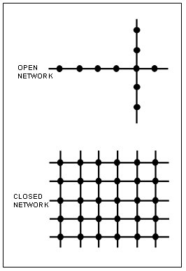
Figure 3-18. Signal Networks.
The previous sections have discussed the concepts of control of isolated intersections as well as maintaining vehicle progressions on arterials and in a grid system. The following discussion on the need for signal coordination is adapted from Gordon (14).
While coordination of adjacent signals often provides benefits, the traffic systems engineer must decide, in each case, whether better performance will be achieved with coordinated or isolated operation.
When a platoon of vehicles is released from a traffic signal, the degree to which this platoon has dispersed at the next signal (difference from profile at releasing signal) in part determines whether significant benefits can be achieved from signal coordination.
The Traffic Network Study Tool (TRANSYT) has become one of the most widely used models in the United States and Europe for signal network timing. It was developed in 1968 by Robertson of the UK Transport and Road Research Laboratory (TRRL) (15), which has since released several versions. This handbook discusses TRANSYT-7F (16), where "7" denotes the seventh TRRL version, and "F" symbolizes the Federal Highway Administration's version using North American nomenclature for input and output. While features of TRANSYT-7F are discussed later in the section, the present discussion relates to the TRANSYT platoon dispersion model.
The model represents the dispersion of a vehicle platoon departing from a signalized intersection as illustrated in Figure 3-19 (16). The figure also shows percentage saturation (a measure of volume) as a function of time at three points along the roadway when no downstream queue is present.
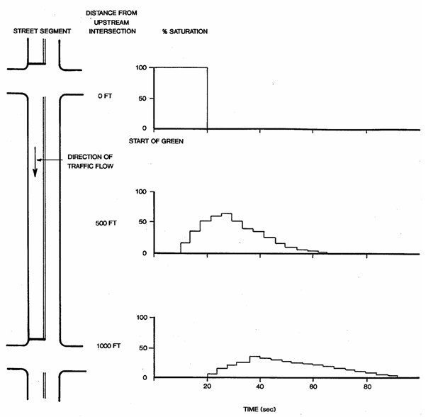
Figure 3-19. Simple Case of Platoon Dispersion.
TRANSYT assumes that the average flow demand at an approach remains constant, i.e., the flow patterns for each cycle repeat. For each computation time interval t, Table 3-9 (16) provides the analytical model for the arrival flow at the downstream stopline. Table 3-10 shows recommended values of platoon dispersion factor (PDF). PDF is a function of travel time to the downstream signal and roadway impedance to traffic flow or "friction". Based on the TRANSYT model, Figure 3-20 (17) depicts the reduction in delay as a function of travel time and PDF.
|
and "a" is a constant, called the platoon dispersion factor (PDF). |
| PDF Value | Roadway Characteristics | Conditions |
|---|---|---|
| .5 | Heavy friction | Combination of parking, moderate to heavy turns, moderate to heavy pedestrian traffic, narrow lane width. Traffic flow typical of urban CBD. |
| .35 | Moderate friction | Light turning traffic, light pedestrian traffic, 11 to 12 ft (3.4 to 3.7 m) lanes, possibly divided. Typical of well-designed CBD arterial. |
| .25 | Low friction | No parking, divided, turning provisions 12ft (3.7 m) lane width. Suburban high type arterial. |
Two general techniques are commonly used to determine coordination needs:
- Information from prior research and experience, and
- Simulation.
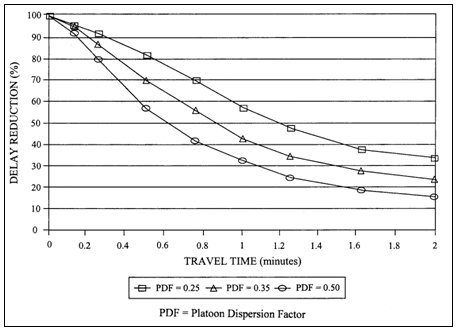
Figure 3-20. Benefits of Signal Coordination
Information from Prior Research and Experience
A number of simple criteria have been used that do not directly incorporate a platoon dispersion model. These include:
- Reduction in the queue (18)
- K = Q/(200(1 + t))
Where:
K = reduction in the queue (number of vehicles)
Q = travel volume (number of vehicles/hr)
T = travel time between intersections (minutes) - Criterion for good progression (19)
Good progression when signal spacing is fairly uniform and
0.40 < Travel time /cycle length < 0.60 - Criterion for coordinating signals (20)
Coordinate signals within 0.5 miles - Criterion for coordinating signals (21)
I = V/L, I > 0.5
Where V = two way peak hour link volume (VPH)
L = Link length (feet)
Chang and Messer developed the intercoordination desirability index (22) described below:
t = link travel time in minutes
qMAX = straight through flow from upstream intersection (VPH)
qT = sum of traffic flow at the downstream approach from the right turn, left turn, and through movements of the upstream signals, divided by the number of arrival links at the upstream intersection.
N = Number of arrival lanes feeding into the entering link of the downstream intersection.
I may range from 0 to 1.0. Interconnection is recommended when I exceeds 0.35.
These criteria may also be employed to establish boundaries between sections of coordinated signals.
Simulation
Simulation is often used to determine coordination requirements and benefits, particularly when performed in connection with retiming of traffic signals. The systems engineer may employ a general model such as CORSIM, together with a signal timing program, or may use the evaluative features of a signal timing program such as TRANSYT 7F. In the latter case, coordination requirements and section boundary identification may be directly coordinated with the signal retiming effort.
A key issue is whether a major intersection operating at near capacity should be coordinated with a series of minor intersections (which by themselves might operate at a lower cycle length) or whether it should operate as an isolated intersection with its own cycle (17).
Time-Space Diagram
Figures 3-21 (a) and 3-21 (b) show this traffic flow control concept via a time-space diagram. Definitions used in this diagram include:
- Green band - The space between a pair of parallel speed lines which delineates a progressive movement on a time-space diagram.
- Band speed - The slope of the green band representing the progressive speed of traffic moving along the arterial.
- Bandwidth - The width of the green band in seconds indicating the period of the time available for traffic to flow within the band.
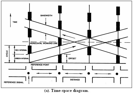
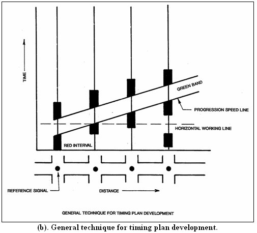
Figure 3-21. Time-Space Diagram And Graphic Technique.
Timing Plan Elements
Operation of a control system for an arterial street (or open network) requires a timing plan for all signals in the system, which consists of the following elements:
- Cycle length - This normally is the same (or some multiple) for all signals in the system or section (subset of a system). The intersection with the longest cycle length requirements (as calculated via methods in section 3.7) usually governs the system cycle length.
- Splits - The length of the various signal phases must be calculated for each intersection. Phase lengths (splits) may vary from intersection to intersection.
- Offset - An offset value must be calculated for each intersection. One definition of offset is the start time of main street green relative to the green interval start for a master intersection in the system.
Figures 3-21 (a) and 3-21 (b) depict an ideal case of equal intersection spacing and splits at all intersections. When this does not occur, the bandwidth becomes narrower than the green interval at some or all signals, as shown in Figure 3-22 (11).
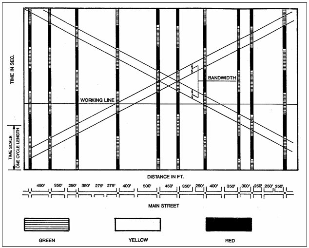
Figure 3-22. Typical Time-Space Diagram.
Traffic Flow Variations
A timing plan is developed for a specific set of traffic conditions. When these change substantially, the timing plan loses effectiveness.
Two basic types of traffic flow variations can occur:
- Traffic flow at individual intersections - volumes can increase or decrease at one or more signal locations. These changes can alter the cycle length or split requirements at the affected intersections.
- Traffic flow direction - flow volume can vary directionally on a two-way arterial. Table 3-11 shows the 3 basic conditions, their normal times of occurrence, and associated timing plans.
Time of day control techniques often provided at least 3 timing plans (A.M., off-peak, P.M.). Traffic-responsive control systems can automatically select timing plans at shorter intervals based on measured traffic flow and select from a greater number of plans.
| Conditions | Normal Time of Occurrence | Timing Plan Progressive Movement |
|---|---|---|
| Inbound flow exceeds outbound flow | A.M. peak | Inbound |
| Inbound flow approximates outbound flow | off-peak | Inbound and outbound equally |
| Outbound flow exceeds inbound flow | P.M. peak | Outbound |
Timing Plan Development
Basic techniques for developing timing plans include:
Manual calculations and / or graphic analysis determine cycle lengths, splits, and offsets.
Offline computer software models make required calculations. Offline indicates that timing plans are generated from traffic data collected earlier. Plans are stored for use during an appropriate time-of-day or may be selected on a traffic-responsive basis using data from traffic system detectors.
Manual Techniques
With the advent of software to develop timing plans, this technique is no longer recommended. The exercise, however, provides insight into timing plan development. Developing an arterial signal system timing plan manually requires collecting the following data:
- Geometric
- Intersection spacing (stopline to stopline), and
- Street geometrics (width, lanes, and approaches).
- Traffic flow
- Volumes, including turning movement counts,
- Flow variations, and
- Speed limitations.
Table 3-12 shows a series of steps leading to manual development of a timing plan.
| 1. Prepare a graphic display of the signal system, similar to figure 3-21 or 3-22. 2. For each timing plan, examine flow conditions at each intersection and evaluate cycle length and split. Use the methods discussed under isolated intersections. Consider increasing volumes to account for seasonal differences and increases in the next 3 to 5 years. Five (5) percent typically accounts for seasonal differences. Calculate optimum cycle length and phase interval for each signal. The longest cycle length usually becomes the system cycle. 3. Conduct a graphic analysis to determine offsets for each timing plan. The graphical analysis proceeds as follows (refer to figure 3-21): a) Identify the signal with the smallest main street green phase split. b) Draw a progression speed line and provisional green band beginning at the start of main street green at this signal. . This speed line will have a slope representing the desired progression speed. *c) Draw a horizontal working line through the center of either a red or green interval for the reference signal. *d) Center either a red or green signal. interval on the horizontal working line (as required to obtain the greatest width of the green bands) to achieve an equal bandwidth for each flow direction. *e) Usually the provisional green band defined by the progression lines plotted in step (b) will not pass through all the green phase intervals plotted in step (d). For this case, adjust the provisional green band by drawing progression lines parallel to the original lines. Space these lines to define the widest bandwidth remaining within the green phase of all signals. *f) Modestly alter the progression line slope about the signal identified in step (a) to determine whether small changes can increase bandwidth. *g) The preceding step results in a timing plan that provides equal bandwidths for each flow direction. If desired, modify this result to favor 1 flow direction.* Applies to 2-way progression shown in Figures 3-21 (a) and 3-22. |
As a general rule, the time-space diagram resulting from Table 3-12 will have the beginning of green occurring at:
- Every other signal, i.e., single alternate, or
- Two adjacent intersections, i.e., double alternate, or
- Three adjacent intersections, i.e., triple alternate.
The beginning of greens may not exactly coincide but will usually approximate one of the three patterns. Figure 3-21 (a) shows single alternate offset timing.
Consider the manual method in Table 3-12 as a trial- and-error procedure. For example, if the resulting progression speeds prove too slow or fast, adjust the system cycle length. A 15 percent decrease or 25 percent increase may provide the desired progression speed without significantly increasing delay. Also, modify phase timing to favor straight-through movements. A protected-permissive left-turn operation may reduce the time initially calculated for protected only left-turn phases. The modified timing plan may produce better results.
Offline Computer Techniques
Most signal timing programs provide signal timing parameters based on one or more optimization criteria such as a combination of stops and delay or maximization of bandwidth on a time-space diagram. In addition to the signal timing parameters, the programs often provide an estimate of measures of effectiveness such as stops, delays, emissions, fuel consumption and level of service. Graphical outputs may include time-space diagrams. In some cases the timing program may be coupled to a simulation that shows microscopic traffic flows. Comparative evaluations for some of these programs are provided in References 23 and 24. The following signal timing programs are commonly used by traffic engineers.
These discussions are provided as illustrations of the technology and are not intended as recommendations. As these and similar products continue to be improved, the reader is advised to contact the supplier for the latest capabilities of these products.
TRANSYT 7F
TRANSYT-7F (16) is a signal timing optimization program and a powerful traffic flow and signal timing design tool. The TRANSYT platoon dispersion model was discussed earlier in this section.
Using standard traffic data timing parameters as input, it can both evaluate existing timing and optimize new plans to minimize either:
- A linear combination of weighted delays, stops, and queue spillback, or
- Total operating cost.
This program has been extensively used in the past and has been updated to a more user-friendly format. Optimization techniques now include the hill climb method (provided in earlier versions) and genetic algorithm optimization. Treatment of queue spillback and traffic actuated signals has been added.
TRANSYT-7F also provides the capability to optimize perceived progression by progression opportunities (or PROS), which simply represent opportunities to get through consecutive intersections on green. Thus, signal timing may be designed for PROS alone, in which case splits remain fixed, or the PROS / DI policy yields a combination of wide bands, while still trying to lessen the disutility index. With PROS, the user can request an explicit time-space type design.
TRANSYT-7F has been used extensively for signal timing in the U.S. Numerous users have reported benefits in using this program for signal timing. Since 1983, California has implemented the Fuel-Efficient Traffic Signal Management (FETSIM) program and widely used TRANSYT-7F to optimize signal timing. Estimated benefits from the new signal timing in 61 California cities and one county show reduced (25):
- Vehicle delay (15 percent),
- Stops (16 percent), and
- Overall travel time (7.2 percent).
Synchro
This commonly used signal timing program has many user friendly features including interconnectivity to map backgrounds, more than eight phase capability and easy connectivity to traffic systems supplied by several vendors (26). Cycle and split optimization models are based on Highway Capacity Manual techniques. Actuated intersections are modeled.
PASSER
The PASSER (27) program suite consists of the following:
- PASSER II-90 - This program computes signal timing for a single arterial based on optimization of arterial bandwidth.
- PASSER III-98 - PASSER III-98 computes optimal signal timing for diamond intersections.
- PASSER IV-96 - PASSER IV-96 computes signal timing for a network based on arterial bandwidth optimization.
aaSIDRA
A version of aaSIDRA (28) based on the U.S. Highway Capacity Manual is available. aaSIDRA models actuated intersections and unsignalized intersections including stop sign controlled approaches and signalized pedestrian crossings, right-turn on red and protected-permitted left turns.
Considerations for Closed Networks
When two arterials cross at an intersection, a signal timing interlock must occur for progression along both arterials. Both must use the same cycle length and the timing plan must use as a reference point the timing at that intersection.
Signal timing in networks conventionally features a common cycle length. The closed topology of the network requires a constraint on the offsets, however. The sum of offsets around each loop in the network must sum equal integral number of cycle lengths. Figure 3-23 provides the node definitions for the following relationships:
DAB + DBC + DCF
+ DFE + DED + DDA = n1
C |
(3.18) |
DAB + DBE + DED
+ DDA = n2 C |
(3.19) |
DBC + DCF + DFE
+ DEB = (n1 - n2) C |
(3.20) |
Need for Signal Retiming
The following discussion is adapted from Reference 29.
With the exception of traffic responsive and adaptive traffic control systems, traffic systems require retiming of the signals from time to time.
The literature provides ample evidence to indicate that signal retiming provides very important and cost effective benefits (17, 25, 30, 31, 32).
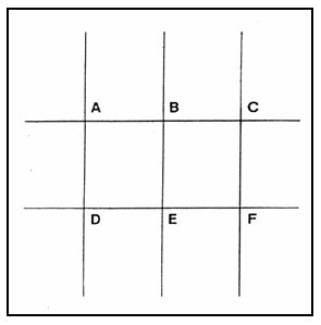
Figure 3-23. Closed Network Node Definitions.
Factors that lead to the need for signal retiming may include:
- Changes in local or area wide traffic demands.
- Changes in peak period volumes.
- Changes in directional flow.
- Local land use changes.
- Change in intersection geometry.
- Change in number or use of lanes.
Signals will require retiming when the project includes major changes to the traffic signal system. Such changes may include:
- Introduction of coordination.
- Addition of local actuation.
- Addition of system traffic responsive capability.
- Introduction of transit priority.
Traffic signal system engineers use these factors, as well as the following, to identify the need for signal retiming:
- Accident experience.
- Comments and complaints by the public.
- Observations of signal timing performance and congestion patterns.
Observations may include:
- Cycle failure (inability of a vehicle to pass through the intersection in one signal cycle) is a key indication of a saturated phase.
- Spillback from turning bays into general use lanes.
- Delays that may be incompatible with the volume to capacity ratio (V/C). For example, unduly long cycle lengths or improper splits may lead to excessive delay when minimal flow is observed during other portions of the green time for the phase.
- Imbalance in green time, i.e. high demand approach vs. low demand approach.
If signals have not been retimed within five years, the probability is high that retiming will provide significant improvement in most cases. In areas where growth or traffic generation changes are significant, more frequent timing may be appropriate. The simulation and signal timing programs, if used on a pilot section of the network, may be used to determine the need for signal retiming.
Determination of Central System Control Category
A new or improved central traffic control system may be needed to satisfy the following requirements:
- The current system is obsolete or can no longer be maintained in a cost effective way.
- A new or modified system is required to achieve such objectives as field equipment monitoring, field device interchangeability (NTCIP), communication with other ITS or information centers and interoperability with other traffic management centers.
- A control strategy resulting in a higher level of traffic system performance than currently exists is required.
Five categories of coordinated control in addition to uncoordinated control have been identified to support the last requirement. The general capability for these categories is identified in Table 3-13. The functions for these categories and guidance for their selection is provided in Table 3-14 and is further discussed below. The local intersection control strategies discussed in Section 3.7 may be used with any of these categories, except for traffic responsive and traffic adaptive control. System installation and operating costs increase with more intensive detector and communication requirements.
| System Category | Features | Implementation Requirements |
|---|---|---|
| Uncoordinated Control |
|
|
Time Base Coordinated Control
|
|
|
Interconnected Control
|
|
|
Traffic Adjusted Control
|
|
|
Traffic Responsive Control
|
|
|
Traffic Adaptive Control
|
|
|
Modern traffic controllers that are not interconnected by wireline or wireless means provide the capability for time base coordination (TBC). Timing plans must be implemented and checked by trips to the field. This category of control does not provide status information to the TMC.
Interconnected control systems provide the capability for wireline or wireless communication with the TMC. They enable the TMC to monitor the condition of intersection equipment and to download timing plan changes. In addition to time-of-day timing plan selection, the operator may select a timing plan at any time. System detectors, if provided at all are used for general traffic monitoring by the operator and for planning purposes.
These systems usually provide for three or more weekday timing plans and other plans that may be required for weekends, holidays, special events or traffic diversion. The capability for this type of operation is provided by most commercially available traffic control systems.
| UNCOORDINATED CONTROL a. Isolated signal operation with local actuation. TIME BASE COORDINATED CONTROL a. Used where time of day / day of week (TOD/DOW) coordination is desired without the installation of physical communication media. INTERCONNECTED CONTROL a. Provides capability to monitor proper operation of traffic signals. TRAFFIC ADJUSTED CONTROL a. Detector surveillance necessary for database development where
use of more than four weekday timing plan changes is contemplated. TRAFFIC RESPONSIVE CONTROL a. Provides capability to respond to short term traffic flow irregularities. TRAFFIC ADAPTIVE CONTROL a. Provides capability to respond to random or very short term
traffic flow irregularities. |
Traffic adjusted control provides a relatively slow capability to automatically select timing plans using data from traffic detectors. Control is usually provided by the UTCS First Generation Control Algorithm or by algorithms provided by closed loop systems. The UTCS algorithm selects an entire timing plan based on sensed conditions. Closed loop systems change cycle, split and offset separately according to sensed traffic conditions. These algorithms are described later in this chapter. System time constants and timing plan change algorithms require a few minutes before the timing plan change can be effected. Thus timing plan changes are usually made at greater than 15 minute intervals, and flow disturbances may be experienced during periods when these changes are being made. System detectors are required. As a general rule, the average number of system detectors is approximately equal to the number of intersections. These detectors may also be used to provide planning data; however, if planning functions are required, it is preferable to have full lane detector coverage for the sampled locations. The capability for traffic adjusted control operation is provided by most commercially available traffic control systems.
Traffic responsive control systems may change the split at each phase of the traffic signal cycle based on traffic measurements upstream of the intersection. Small changes in cycle time and offset may be made during time periods ranging from each cycle to a few minutes. The greatest benefit for traffic responsive systems is the ability to react to non-schedulable events or unpredictable events such as incidents. Other benefits include the ability to adjust timing plans without the requirement to manually generate new plans.
Systems such as SCOOT and SCATS (described later in the chapter) are examples of commercially available traffic responsive systems. While detector requirements differ with system implementation, SCOOT generally requires one detector per signalized approach. SCATS uses one detector in each major approach lane.Traffic adaptive control strategies such as RHODES and OPAC (described later in this chapter) do not employ defined traffic cycles or signal timing plans. They utilize traffic flow models that predict vehicle arrivals at the intersection, and adjust the timing of each phase to optimize an objective function such as delay. Because they emphasize traffic prediction, these systems can respond to the natural statistical variations in traffic flow as well as to flow variations caused by traffic incidents or other unpredictable events. Intersection control equipment for adaptive systems is often more complex than for the other control categories.
Online Network Traffic Control Techniques
Online computer techniques use a computer traffic control system to:
- Collect data on traffic flow conditions,
- Make calculations to determine a desired timing plan, and
- Implement or adjust the timing plan in short time intervals such as each phase or cycle or when a different plan is required. Conventional traffic control systems select a plan from a stored plan library based on current conditions. Traffic responsive and adaptive systems provide for dynamic or real-time timing plan generation.
UTCS Control
Starting in the 1970's, a large number of U.S. cities implemented computer traffic systems using technology developed by the FHWA (under a number of related research programs) (33, 34, 35, 36, 37) and termed the Urban Traffic Control System (UTCS). FHWA established a testbed in Washington, DC which served as the prototype for many later systems. UTCS systems implemented in the 1970's and through much of the 1980's possessed the following characteristics:
- Minicomputer based central computer controls signals with commands for discrete signal state changes. Timing for commands provided at intervals of approximately one second.
- Signal timing plans stored in the central computer. Timing plan changes may result from:
- Traffic responsive operation (based on detector inputs from the field),
- Time-of-day selection, or
- Operator commands (manual).
- Computation of volume and occupancy from detector data each minute. This data was used for reports and for archival purposes. The data is smoothed with a filter for use with the traffic responsive control algorithm and for the graphical display.
- A first generation traffic responsive control algorithm for changing background timing plans. Table 3-15 describes the UTCS first generation traffic responsive control algorithm. Reference 2 provides a more detailed discussion of the UTCS control algorithms.
The central computer for the initial family of computer traffic control systems provided a signal to the field controller to change each interval or phase of the traffic signal control cycle; however most of the current traffic control systems download timing plans to the field controller. The timing plans are stored in the field controller, which then times out each traffic cycle. Implementation technique notwithstanding, many of the current traffic control systems employ the UTCS First Generation Traffic-Responsive Control Algorithm described in Table 3-15. These systems are identified in the two-level distributed control block in Figure 1-2. Implementations of current system architectures are described in Chapter 8.
| Signature The basic concept of the traffic-responsive control law associates each prestored timing plan with one or more traffic signatures. This signature comprises an array of numbers, one for each system detector in the subnetwork or section. Each number represents a linear combination of volume and occupancy data for the detector. A column matrix or vector can represent these numbers if ordered in a vertical array. Equation 3.21 represents the vector equation for the signature. Where: VS = Vector representative of the volumes for stored signature
SIG With 2 detectors present (denoted by subscripts 1 and 2), the corresponding scalar equations become:
Match The algorithm then matches real-time traffic data from each subnetwork detector against the signatures and selects the timing plan corresponding to the best match. Matching identifies the signature, which minimizes the sum of absolute values of the difference in each detector's match. Equation 3.24 represents this mathematically: Where: VF = Current smoothed volume The components of the error vector for each signature are summed and the timing plan associated with the signature having the smallest error sum is selected. UTCS permits a limited number of signatures (often 3 or 4) to be matched at any time of day (window). This ensures selection of a viable timing plan. Many UTCS can adjust the test frequency, with the usual period ranging from 4 to 15 minutes. Sometimes, error values relative to each of 2 stored signatures may be close. In this case, random components in the traffic data may cause frequent changes in timing plans. To reduce this oscillation, UTCS permits implementation of a new timing plan only when it provides a significantly lower error than the current signature, i.e., it must show at least a threshold level of error improvement. |
Control Algorithms for Closed Loop Systems
Closed loop systems are identified by the three-level distributed control block in Figure 1-2. A central computer stores and downloads signal timing plans through a field master to a signal controller. It also supervises controller operations. A field master preprocesses detector data prior to upload to the control computer. It also selects the timing plans for traffic responsive control.
The specific signal timing plan selection algorithms vary among system suppliers; however, they generally provide the following features:
- System detectors in a control section are assigned to implement either the cycle, split or offset computation. A system detector may be assigned to one or more computations.
- Selections of cycle, split and offset are made separately. The cycle selection, for example, would typically depend on volume and / or occupancy lying between pre-established thresholds. A cycle length is associated for each range of detector values lying between thresholds. Split and offset thresholds are similarly established.
- In some cases, traffic features such as directionality or queue presence may be used in the computation of cycle, split and offset. System detectors may be assigned to compute these features.
- Provisions are often made for the constraint of cycle, split and offset selections by time of day or by some other means so that the entire timing plan conforms to a plan developed by a signal timing program such as TRANSYT 7F or Synchro.
Balke, et. al. (38) provide a discussion on supplier specific parameter selection issues.
Traffic Responsive Control Systems
Traffic responsive control systems are distinguished from the systems described above in the following ways:
These systems generally respond to changes in traffic on a system-wide basis quite rapidly usually at the next phase of the traffic cycle.
- Except for initialization purposes, storage of precomputed cycle length, splits, and offset is not required, i.e. the system continually computes the traffic control plan.
- Extensive traffic detector instrumentation is required.
The following subsections describe the traffic responsive systems that are currently commonly available.
SCOOT (Split, Cycle and Offset Optimization Technique) (39, 40, 41, 42, 43)
The Transport and Road Research Laboratory (TRRL) in Great Britain developed SCOOT beginning in 1973, and by 1979 implemented it on a full-scale trial in Glasgow.
Based on detector measurements upstream of the intersection, the SCOOT traffic model computes the cyclic flow profile for every traffic link every four seconds (Figure 3-24). SCOOT projects these profiles to the downstream intersection using the TRANSYT dispersion model (Equations 3.16 and 3.17 in Table 3-9). Table 3-16 summarizes the SCOOT optimization process.
| Timing Parameter | Conditions |
|---|---|
| Offset | A few seconds before every phase change, SCOOT determines whether
it is better to: |
| Split | Once per cycle, SCOOT determines whether the performance index (PI) can be improved by reducing or increasing each offset by 4 seconds. The PI is usually a weighted sum of stops and delays. |
| Cycle | SCOOT varies the cycle time by a few seconds every few minutes to try, if possible, to keep the maximum degree of saturation below 90 percent on the most heavily loaded phase. |
SCOOT contains provisions for weighting capabilities in the signal optimizers to give preference to specific links or routes.
Recent additions to SCOOT have enhanced its performance under congestion and saturation conditions. Table 3-17 describes the enhanced SCOOT features. Section 8.3 describes SCOOT benefits, SCOOT detector deployments and additional application information.
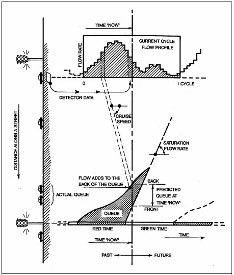
Figure 3-24. Principles of the SCOOT Traffic Model.
| Features | Description |
|---|---|
| Congestion Offsets | Under congestion conditions, the best offset may facilitate a particular movement (to prevent spillback across an intersection or for other reasons). Under congestion situations, SCOOT provides congestion offsets that replace the criterion for optimizing the PI with a specially designed offset. Information from another link may also be used to implement offsets under congestion conditions. |
| Gating Logic | Gated links are designated to store queues that would otherwise
block bottleneck links. Thus, green time can be reduced on a gated
link as a function of saturation on a remote bottleneck link. Green time reduction to a prescribed level is initiated when the problem is identified in the problem area as measured, for example, by degree of saturation. The green time is reduced as the problem becomes more severe, but a specified minimum green time is preserved. |
| Automatic Calibration of Saturation Occupancy | Early versions of SCOOT required the system operator to supply the
appropriate value of saturation occupancy. The latest version of SCOOT
provides this capability automatically, which:
|
| Bus Priority | Bus priority can be granted using either simple bus detectors or by means of an advanced vehicle location system. The latter capability allows priority (green extension or advance) to be implemented by importance (e.g., granting priority only to late buses). Priority may be constrained by the detection of congestion on computing phases affected by priority. |
| Emissions | Emissions estimates may be used as the objective function in the computation of offsets. |
SCATS (Sydney Co-ordinated Traffic Control System)
The Sydney Coordinated Adaptive Traffic System (SCATS) (44, 45, 46, 47) was developed by the Roads and Traffic Authority (RTA) of New South Wales, Australia. A real-time area traffic control system, it adjusts signal timing in response to variations in traffic demand and system capacity, using information from vehicle detectors, located in each lane immediately in advance of the stopline.
SCATS uses two levels of control: strategic and tactical. Strategic control determines suitable signal timings for the areas and sub-areas based on average prevailing traffic conditions. Tactical control refers to control at the individual interaction level. Table 3-18 describes the functions of each control level.
| Level | Description |
|---|---|
| Strategic |
|
| Tactical |
|
SCATS has seen application in many cities throughout the world. Its first application in North America was in conjunction with the Autoscope video detector in Oakland County, Michigan, in the FAST-TRAC project.
SCATS currently has three levels of control: local, regional, and central. SCATS distributes computations between a regional computer at the traffic operations center and the field controller. Implementation in the US therefore requires special adaptation of an existing traffic controller to incorporate the SCATS field processing functions. Additional information on architecture is given in Section 8.3.
Several studies have been performed to measure the effectiveness of SCATS. RTA simulated a comparison of SCATS with a TRANSYT optimized fixed time system (45) and claims the following benefits:
- In the A.M. peak period, with traffic flow not deviating about the average, SCATS shows little improvement in delay and approximately 7-8% fewer stops.
- In the A.M. peak period, when traffic flows fluctuate 20% to 30%
from the average, SCATS shows improvements as follows:
- 8% in total vehicle stops along main roads,
- 3% in total traffic delay,
- 3% in total fuel consumption, and
- 3-6% reduction in pollutant emission (CO, HC and NOx)
A study by the City of Troy, Michigan (48), found the following benefits
- Travel time reductions
- A.M. Peak: 20%
- Off Peak: 32%
- P.M. Peak: 7%
- 20% reduction in stopped vehicle delay
- Although no significant decrease in the number of accidents, the percentage of incapacitating crashes reduced from 9% to 4%
Abdel-Rahim, et al. (49) found the following results in Oakland County, Michigan. The results indicated travel time decreased 8.6% in the morning peak direction of travel and 7% in the evening peak direction of travel. Off peak and non-peak direction travel times were also improved, decreasing 6.6 to 31.8%. The improved travel times observed on this major arterial, however, lead to increased average delay on minor arterial approaches:
- A.M. Peak travel time reduction: 8.6%
- P.M. Peak travel time reduction: 7%
- Off-Peak and non-peak direction travel time reduction: 6.6% - 31.8%
- Increased average delay on minor streets
Major operational advantages of SCATS include:
- The ability to automatically generate timing plans thus saving the operating agency the effort of performing this task, and
- The ability to automatically calibrate detectors, thus avoiding this task during system test and grooming
Section 8.3 provides additional application information on SCATS.
Traffic Adaptive Control Systems
Traffic adaptive control systems feature sufficient surveillance capability to provide a detailed profile of traffic approaching an intersection. Since control decisions are made during each phase, no explicit cycle length is defined in the control algorithm.
RHODES
The RHODES (50) architecture is based on decomposing the control-estimation problem into three hierarchical levels: (1) intersection control; (2) network control; and (3) network loading. Figure 3-25 shows the RHODES architecture. At the lowest level, intersection control, traffic flow predictions and signal phase and duration decisions are made based on observed vehicle flows, coordination constraints, flow predictions and operational constraints that are typically established by the traffic engineer. These decisions are currently made on a second-by-second basis.
At the middle level, the network control level, predictions of platoon flows are used to establish coordination constraints for each intersection in the network. These decisions are made periodically at an approximate interval of 200-300 seconds depending on the network characteristics.
At the highest level, the network loading level predicts the general travel demand over longer periods of time, typically one hour. These demands can be used proactively to determine future platoon sizes at or near the control boundaries. Many of the anticipated benefits of Advanced Traveler Information Systems (ATIS) and / or Dynamic Traffic Assignment (DTA) can be used for traffic control and management through the network loading level.
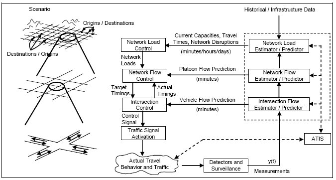
Figure 3-25. The RHODES Hierarchical Architecture.
OPAC
OPAC (Optimized Policies for Adaptive Control) (51) is a set of algorithms that calculate signal timings to minimize a performance function of stops and delays. OPAC was developed in a series of versions. OPAC III and OPAC IV are revisions that have been physically implemented.
OPAC III provides local intersection control. It implements a "rolling horizon" strategy to make use of flow data that are readily available from existing detection equipment without degrading the performance of the optimization procedure. In this version, the stage length consists of n intervals. The stage is called the Projection Horizon (or simply Horizon) because it is the period over which traffic patterns are projected and optimum phase change information is calculated. The horizon is typically taken to be equal to an average cycle length.
Figure 3-26 is an illustration of the rolling horizon procedure. From detectors placed upstream of each approach, actual arrival data for k intervals can be obtained for the beginning, or head, portion of the horizon. For the remaining n-k intervals, the tail of the horizon, flow data may be obtained from a model. A simple model consists of a moving average of all previous arrivals on the approach. An optimal switching policy is calculated for the entire horizon, but only those changes which occur within the head portion are actually being implemented. In this way, the algorithm can dynamically revise the switching decisions as more recent (i.e., more accurate) real-time data continuously become available.
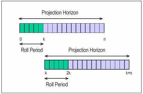
Figure 3-26. Implementation of the Rolling Horizon Approach in
OPAC.
By placing the detectors well upstream of the intersection (10 to 15 sec. travel time) one can obtain actual arrival information for the head period. This allows for a more correct calculation of delay for any given phase change decision. At the conclusion of the current head period, a new projection horizon containing new head and tail periods is defined with the new horizon beginning at (rolled to) the termination of the old head period. The calculations are then repeated for the new projection horizon. The roll period can be any multiple number of steps, including one. A shorter roll period implies more frequent calculations and, generally, closer to optimum (i.e., ideal) results.
OPAC IV is a network version of OPAC. OPAC was developed from the outset as a stand-alone "smart controller" that can be used as a building-block in a distributed control system. No explicit coordination features were imbedded; however, the algorithm has inherent self-coordination capabilities due to the tail model in the projection horizon. A system using these capabilities was successfully installed on Rt. 18 in New Jersey. As part of the RT-TRACS project, the OPAC control logic was expanded to include, at the option of the user, an explicit coordination / synchronization strategy that is suitable for implementation in arterials and in networks. This version is referred to as Virtual-Fixed-Cycle OPAC (VFC-OPAC) because from cycle to cycle the yield point, or local cycle reference point, is allowed to range about the fixed yield points dictated by the virtual cycle length and the offset. This allows the synchronization phases to terminate early or extend later to better manage dynamic traffic conditions. VFC-OPAC consists of three-layer control architecture as follows:
Layer 1: The Local Control Layer implements the OPAC III rolling horizon procedure. It continuously calculates optimal switching sequences for the Projection Horizon, subject to the VFC constraint communicated from Layer 3.
Layer 2: The Coordination Layer optimizes the offsets at each intersection (once per cycle). This is done by searching for the best offset of the PS within a mini-network. Since this is carried out in a distributed fashion at each intersection, each SS will, in its turn, also be considered as a PS of its own mini-network.
Layer 3: The Synchronization Layer calculates the network-wide virtual-fixed cycle (once every few minutes, as specified by the user). The VFC is calculated in a way that provides sufficient capacity at the most heavily loaded intersections while, at the same time, maintaining suitable progression opportunities among adjacent intersections. The VFC can be calculated separately for groups of intersections, as desired. Over time the flexible cycle length and offsets are updated as the system adapts to changing traffic conditions.
Saturated Flow Conditions
A saturated flow condition develops when demand at a point (or points) in a network exceeds capacity for a sustained period. This condition reveals itself at an intersection through the development of long queues, which may reach from one intersection to another.
When this condition occurs, traffic cannot move even when it receives a green light, and jam conditions develop.
To clear traffic during jam conditions requires a different concept of control. Most of the control techniques described up to this point will fail in an oversaturated traffic environment. In a network, two levels of saturated flow can occur:
- Saturated flow at a limited number of signalized intersections, and
- Widespread saturation.
The following control concepts deal with these types of saturated flow.
Under NCHRP-sponsored Project 3-18, researchers at Polytechnic University developed guidelines for improving traffic operations on oversaturated street networks and documented them in NCHRP Report 194, Traffic Control in Oversaturated Street Networks (52). The researchers used simulation and analytical studies, field tests, and national surveys to develop the guidelines. The report enumerates several candidate treatments:
- Minimal response signal remedies - intersection,
- Minimal response signal remedies - system,
- Highly responsive signal control,
- Enforcement and prohibition,
- Turn bays and other non-signal remedies,
- Major lane assignments, and
- Disruptions to the traffic.
Arterial and network signal timing programs primarily optimize flow on unsaturated arterials and networks. These concepts provide progressive greenbands for vehicles and minimize a network performance index such as delays and stops.
However, widespread network saturation requires special coordination techniques (52, 53, 54). Quinn expresses the coordination principles (53):
A common feature of the strategies is a change in the basic concept of what the offset between signals is supposed to accomplish. Instead of providing for forward progression of vehicle platoons, the signal timings at an upstream junction are determined by the start of green downstream, and the time taken for the front of a queue to move upstream and clear the upstream intersection. Thus, the order of calculation of signal timings is opposite to the flow of congested traffic, so that the term 'reverse offsets' is sometimes used. (Figure 3-27)
The NCHRP 3-38 study broadened these concepts. Reference 55 describes the basis for developing signal timing plans and strategies along with examples. The reference also describes other forms of metering such as external metering (Figure 3-28) and release metering (controlled rate of discharge from parking facilities).
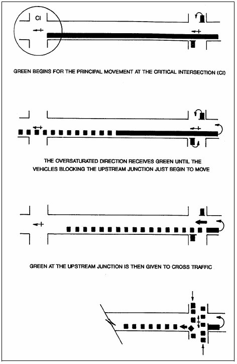
Figure 3-27. Reverse Progression Signal Offset.
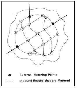
Figure 3-28. External Metering.
Lieberman et al (56) describe a control policy for oversaturated approaches as follows:
The policy principles are: (1) the signal phase durations "meter" traffic at intersections servicing oversaturated approaches to control and stabilize queue lengths and to provide equitable service to competing traffic streams; and (2) the signal coordination (i.e. offsets) controls the interaction between incoming platoons and standing queues in a way that fully utilizes storage capacity, keeps intersections clear of queue spill-back and maximizes throughput.
A number of strategies have been developed to improve the timing of these networks (57, 58). These strategies generally attempt to accomplish the following.
- Identify the queue and the queue discharge time.
- Identify the downstream storage available for queue discharge.
- Maximize throughput by avoiding the provision of green time that cannot be used or is inefficiently used because traffic cannot flow during thee green periods.
The algorithms generally require a search for possible solutions. Techniques such as genetic algorithms may be used to facilitate the search.
Girianna and Benekohal (59) provide an algorithm to manage local queues by distributing them over a number of signalized intersections, and by temporarily spreading them over several signal cycles. Girianna and Benekohal (60) describe a procedure for dissipating queues on a two-way arterial.
Where widespread saturation exists, one perspective views the area as possessing a capacity to contain vehicles and manages entry flow to this capacity. Smeed provides equations to determine the capacity (61). Godfrey (62) illustrates the relationships among:
- Number of vehicles in the network,
- Throughput of the network in vehicle mi/hr (km/hr), and
- Average vehicle speed.
Figures 3-29 and 3-30 illustrate the relationship for the town center of Ipswich, England (62). The figures show that current operation provides less than maximum potential throughput at an average speed of 7.4 mi/hr (11.9 km/hr). The shape of Figure 3-29 resembles the freeway speed versus density relationship and the shape of Figure 3-30 resembles the freeway volume versus speed relationship. These curves suggest improvement of network use and travel speed through a combination of external and release metering to limit the number of vehicles accessing the network to the number that represents a maximum throughput condition.
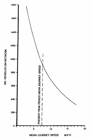
Figure 3-29. Relationship Between Mean Journey Speed and Number of Vehicles on Town Centre Network.
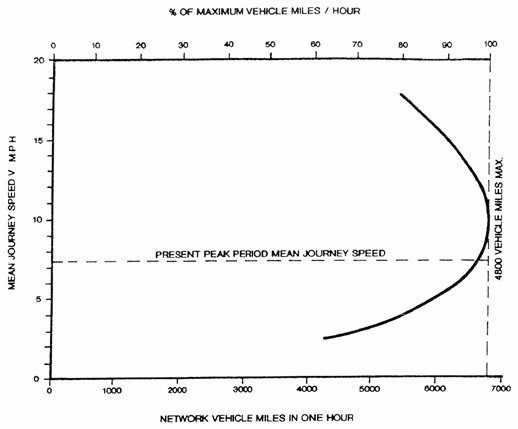
Figure 3-30. Relationship Between Mean Journey Speed of Vehicles
and Total Vehicle Mileage on Network.
Management policies for controlling widespread congestion may make use of regulatory or pricing approaches. Both of these techniques require participation at the highest political levels in the jurisdiction involved.
Regulatory Approaches
After the events of September 11, 2001, New York City restricted the entry of vehicles to the central business districts of Manhattan during certain periods of the day. This significantly reduced congestion during the period that these controls were in effect.
Congestion Pricing Approaches
While a number of localities have used vehicle entry pricing to congested areas, the largest scale application of this technique started in central London in February 2003. The daily congestion charge of 5 pounds (approximately $8) resulted in considerably reduced congestion and increased speed in this highly congested area (63). The website (64) describes the collection and enforcement methodology.
Network Simulation
A number of simulations exist for modeling surface street networks. Three of these simulations also model freeway networks. All of these simulation programs have many similar or exactly the same features. The discussions that follow touch on some of the characteristics featured by these models.
CORSIM
CORSIM (65) is a two-part microscopic traffic simulation tool and is a part of FHWA's Traffic Software Integrated System (TSIS). The first part of CORSIM, NETSIM, simulates surface streets, and the second part, FRESIM, simulates freeways. The surface street simulation has the following capabilities:
- Graphical visualization system (TrafVu) displays and animates networks, including traffic flow, signal operation, freeway and surface street incident modeling (accidents, work zones, parking activity), sources / sinks and MOEs.
- Models pretimed and actuated signals.
- Models traffic signals, system and local actuation detectors, sign control (stop and yield), and roundabouts.
- Analyzes the network by continuously tracking all individual vehicles.
- Uses vehicle and driver behavior models.
- Models cars, trucks, and buses.
- Creates text output files for MOEs. The MOEs can be viewed graphically in TrafVu. The model provides travel times, average speed and bus statistics.
- MOEs include Control Delay (can be used to calculate LOS using the HCM method), overall vehicle delay, stops, queues, emissions (CO, HC, NOx), fuel consumption.
SimTraffic
SimTraffic (26) is a Synchro-companion program that allows visual simulation of a surface street traffic network. In SimTraffic, it is possible to create mixed networks of signalized and unsignalized intersections, model both pretimed and actuated intersections, and simulate operation of several intersections by one controller. It is possible to model sections of freeways. SimTraffic models cars, trucks, and pedestrians. SimTraffic allows the user to simulate traffic signal timings developed in Synchro and verify there are no major queues, spillbacks or phasing problems.
Paramics
Paramics (66) is a microscopic traffic simulation system developed by Quadstone Limited. The system has tools for modeling, analysis and processing of surface street and freeway network data. The resulting network can also be displayed visually. The software includes an estimating tool for costs. The software can use bitmapped background or an aerial photograph for network geometric configuration input (to build the network using the bitmap as the background). It has the following features for surface street operation:
- Three-dimensional visualization system.
- Pretimed and actuated signals
- Graphical user interface has network and simulation parameter modification tools
- Analyzes congestion by continuously tracking all individual vehicles on the network (vehicles are released on the links)
- Allows parking lot simulation, illegal or double parking simulation, and incident modeling (disabled vehicles and accidents) including rubbernecking delays on the opposite side of the road.
- Accounts for vehicle type and driver behavior type.
- Models cars, trucks, and pedestrians.
- Can model public transportation, including buses and trains.
- Has capabilities for priority intersection analysis (public transport actuated traffic signals).
- MOEs also include emissions (CO, HC, NOx), fuel consumption and noise pollution.
- Route-cost calculation module (in terms of travel time, distance and tolls).
Paramics is used in the UK, US, Australia, and in the academic environment.
VISSIM
VISSIM (67) is a microscopic traffic simulation model designed to simulate surface streets and freeways. The simulation is time step based, and it monitors all individual vehicle-driver units. The model consists of the VISSIM traffic flow simulation and the CROSSIG control program, which receives the detector input from VISSIM and determines the signal phasing. VISSIM does not have links and nodes-it uses a system of links and link connectors. Infrastructure typically allocated to nodes (signal heads, stop signs, etc.) is allocated to links in VISSIM. VISSIM produces Time-Space and Space-Speed Diagrams, and it creates an animated simulation of the vehicle movement. VISSIM is used in Europe, and, to a lesser extent, in the United States. It has the following features for surface street operation:
- Stop-sign control, pretimed and actuated signals control
- Models signals, ramp meters, detectors, and electronic message signs
- Graphical user interface allows modeling of network geometry. The network can be modeled using a bitmap image as a background.
- Analyzes queues and areas of speed reduction by continuously tracking all individual vehicles on the network, recording position, speed and acceleration of each vehicle for every second.
- Models cars, trucks, and pedestrians
- Can model public transportation, including buses, light rail and heavy rail
- Has capabilities for preemption and priority intersection modeling (buses and light rail). This may require development of an additional program.
- Typical input includes network geometry, traffic volumes, vehicle types and lengths, vehicle speeds, accelerations, signal timings, and bus stop locations and boarding times. The network model can also be imported from the transportation planning model VISUM.
- MOEs include delays, stops, queues, travel times (including delays at signals and bus stop delays), emissions and fuel consumption.
3.9 Special Controls
Closely Spaced Intersections
A special case of arterial street control involves two (or rarely three) intersections so close together that they are better controlled by the same signal controller rather than by separate controllers. A single controller may be advantageous for closely spaced intersections under any of the following conditions:
- The physical spacing between the intersections is small - say 200 feet or less.
- Careful coordination of the signals is necessary to avoid queue spill-back from one intersection that can seriously disrupt operation of the adjacent intersection.
- Both turning and through traffic movements at the upstream intersection constitute major traffic movements requiring progression through the downstream intersection.
- The closely spaced signals do not require coordination with other signals on the arterial, or require coordination only during peak periods.
- Actuated control of the signals is desired.
- One or both intersections operate near saturation during peak periods.
A single controller can provide the following operational advantages:
- The signals can operate in free mode (not coordinated) with all the efficiency advantages of fully-actuated, free operation, while still coordinating the service of major traffic movements at adjacent intersections to provide progression and avoid queue spill-back.
- Progression between intersections can be maintained even under relatively low-volume conditions when it is inefficient to use normal signal coordination due to the need for a fixed cycle length long enough to accommodate pedestrians and traffic fluctuations.
- Critical movements can remain coordinated even when normal signal coordination measures fail (e.g., clocks drift, signal interconnect fails).
- A vehicle approaching an upstream signal on a progressing movement can cause the appropriate phase at the downstream signal to be called or extended as needed.
Figure 3-31 provides an example of how two closely spaced intersections can share a normal eight-phase, dual-ring controller to good effect. Many modern controllers now offer sixteen or more phases in four or more rings, and eight or more overlaps, allowing use of a single controller even when numerous traffic movements need separate phases or overlaps and more than normal dual-ring logic. Some controllers will also support multiple cabinets, each with its own set of detectors (inputs), load switches (outputs), power supply, and conflict monitor.
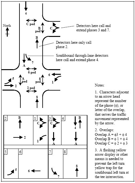
Figure 3-31. Example of One Controller for Two Adjacent Intersections.
As another example, signalized tight diamond interchanges often use one signal controller (68). Such implementations typically involve one of the two phasing arrangements shown in Figure 3-32, or switch between these phasing options as traffic flow patterns change during the day. One phasing scheme uses three phases per ring and is often called Three-Phase Operation. The other uses four phases per ring and is often called Four-Phase Operation.
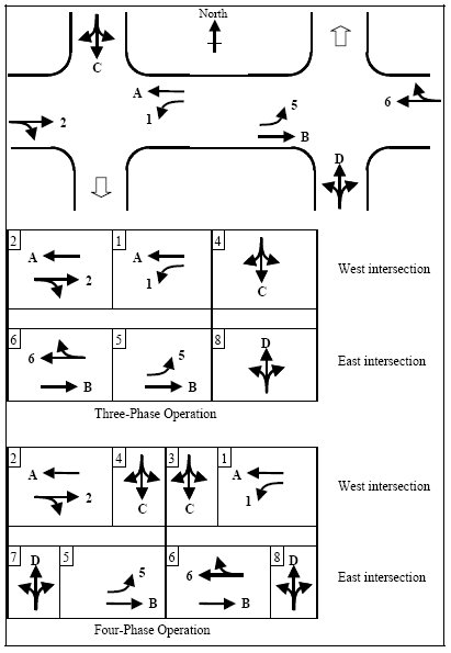
Figure 3-32. Examples of One Controller for a Diamond Interchange.
Three-phase operation gives a green indication to both off-ramps simultaneously, and then serves all through movements followed by both left turns to the on-ramps (and their adjacent exiting-through movements). Desirably, only one barrier is imposed between the two rings (to coordinate the operation of the two intersections even when operating in free mode) following phases 1 and 5. However, some controllers don't allow for single barrier operation, and require a second barrier following phases 4 and 8. In this case both off-ramps receive identical green times.
Three-phase operation is efficient if turning traffic volumes are light, and can minimize the cycle length. However, as turning volumes increase, this scheme can lead to internal queue spillback and operational breakdown.
Higher turning movement volumes (from off-ramps, or to on-ramps) can be accommodated using the four-phase scheme. In this arrangement, the off-ramps are served at different points in the cycle. The exiting-through-and-left movements at the other intersection receive a green indication for part of the off-ramp service time. The green indication for the exiting-through-and-left movements also coincides with part of the green time for entering-through traffic at the adjacent intersection. This avoids internal queue spillback problems.
In four-phase operation, phases 3 and 7 are typically served for a fixed green time, that being the travel time from one intersection to the next. This ensures that the first through vehicles on the surface street do not have to stop at the second intersection, while avoiding wasted time at the second intersection. Efficient use of this fixed phase duration requires the termination of phases 4 and 8 via advance detectors on the off-ramps. Phases 4 and 8 will typically terminate later than phases 5 and 1 respectively, as U turn movements at interchanges are rare and exiting-left-turn traffic has already had ample time to depart. Phases 4 and 8 can have a very short minimum green time.
Both of these diamond interchange phasing schemes make use of overlaps to enable a traffic movement to receive a continuous green display during two or more phases. The overlaps also drive pedestrian displays, at least for pedestrians crossing the surface street. Additional overlaps can enable a controller to be programmed with both phasing schemes simultaneously, using up to 14 phases. Either subset of phases (three-phase operation or four-phase operation) can be selected during a particular timing pattern by omitting the other phases.
Control of multiple intersections with a single controller can also have the following drawbacks, which need to be considered:
- A fault in the controller or other cabinet equipment not duplicated at each intersection can cause both intersections to go into failure-mode flash. Depending on intersection spacing and traffic patterns, this can be undesirable.
- Unless separate cabinets and power supplies are used, a single controller can require relatively long wiring runs which can exceed maximum lengths for voltage drop or detector sensitivity unless special cabling is used.
- It may not be possible to locate a single controller cabinet such that a technician can see all movements at all intersections when troubleshooting or starting the controller.
Directional Controls and Lane Control Signals
To best use existing facilities, consider unbalanced and / or reversible-lane flow. This requires special traffic controls to effect the desired movements. Two basic types of operations using surface street directional controls include:
- Reversible Flow - Dynamically operating a street as one-way inbound,
one-way outbound, or two-way. Applications may include:
- Heavy imbalance of directional traffic flow for relatively short periods such as in and out of central business districts,
- No alternate solutions such as one-way pair or street widening,
- Severe congestion and need to increase directional capacity, and
- Nearby parallel street capable of handling minor directional flow during peak one-way operation.
- Off-center lane movement - Partial reversal of traffic flow where only one or two lanes are reversed. Applications are similar to reversible flow.
Current techniques for controlling directional movement use signs or a combination of signs and lane control signals. Change of operational mode is usually on a time-of-day basis.
Directional control is often used in tunnel and bridge operations for the following purposes:
- Assignment of roadway lanes to prevailing directional traffic flow requirements,
- Control of traffic flow during maintenance operations, and as
- An element in incident response plans.
Reversible lane control has proven the most common use for lane control signals (LCS). Examples include (69, 70):
- Toll booths,
- HOV lanes,
- Reversible transitways on freeways,
- Arena traffic, and
- Parking control
Other applications include:
- Restriction of traffic from certain lanes at certain hours to facilitate merging traffic from a ramp or other freeway, and
- Lane use control for:
- Tunnels,
- Bridges, and
- Freeways.
TheThe MUTCD further defines the signal displays and meaning of indications as described in Table 3-19.
| Display | Definition |
|---|---|
| Steady Downward Green Arrow | Driver permitted in the lane over which the arrow signal is located. |
| Steady Red X | Driver not permitted in the lane over which the signal is located. This signal shall modify the meaning of all other traffic controls present |
| Steady Yellow X | Driver should prepare to vacate the lane over which the signal is located, because the lane control change is being made to a steady Red X indication. |
| Steady white two-way left-turn arrow | Driver permitted to use a lane over which the signal is located for a left-turn. Driver further cautioned that lane may be shared with opposite flow left-turning vehicles. |
| Steady white one-way left-turn arrow | Driver is permitted to use a lane over which the signal is indicated for a left turn (without approaching turns in the same lane) but not for through travel. |
The MUTCD further defines other characteristics of LCS including:
- Display shape and size,
- Visibility distance and angle,
- Separate or superimposed display units,
- Positioning of LCS over lane,
- Longitudinal spacing of LCS over length of controlled roadway, and
- LCS display sequencing and operations.
An ITE equipment and materials standard also exists for LCS (71). It further defines a number of other characteristics including:
- Construction,
- Lens color definitions, and
- Arrow and X shape guidelines.
Many of the factors that govern visibility of CMS messages also apply to LCS.
The most common types of LCS are:
- Fixed-grid fiberoptic, and
- Fixed-grid light emitting diode.
Lane Control Signal Technology is discussed in Chapter 8 of the Freeway Management and Operations Handbook.
Lane control signals are not mandatory for reversible lanes or other purposes; signing often can suffice in these applications. However, properly designed and operated lane control signals generally prove more effective and their use is steadily increasing.
Preemption Systems
Preemption of the normal cycling of a traffic signal may be used:
- To clear traffic from railroad tracks when a train is approaching an at-grade crossing within or adjacent to the signal, and to avoid giving a proceed indication to vehicular and pedestrian movements that cross the tracks, while the crossing is active, and
- To provide a proceed indication to an approaching fire truck or other emergency vehicle, thus reducing delays to such vehicles. Preemption is sometimes used similarly to reduce delays for transit vehicles, but this is rare and signal priority is typically used for this purpose (see following section).
In railroad preemption, a railroad track circuit senses the presence of an approaching train. This presence indication is a steady input to the traffic signal controller and causes the traffic signal to start a preemption sequence that may include the following stages:
- Current vehicular and pedestrian service is terminated immediately,
- A green indication is given to vehicles that may be queued on the railroad tracks, just long enough to allow vehicles to move off the tracks,
- Before the train arrives at the crossing, signal operation changes to either flashing red for all signals (pedestrian indications are dark), or cycling through a subset of the phases - those that do not conflict with the railroad crossing, and
- When the train departs and the presence input goes away, the signal resumes normal operation, but may temporarily operate special timings that help clear a queue of vehicles blocked by the train's crossing.
Emergency vehicle preemption usually involves a different set of actions. When the preemption input is first sensed, or after some fixed delay, current vehicular service is terminated if it conflicts with the emergency vehicle movement, but pedestrian service is usually allowed to complete timing of the Flashing Don't Walk indication. The signal then jumps to the phases that serve the emergency vehicle movement (typically the phase serving a through movement plus any protected left-turn phase in the same direction) and remains in these phases until the preemption input goes away or a maximum timer expires. As with railroad preemption, the signal may be configured to resume normal service at particular phases, or might be configured to start with the phases that will instantly restore the coordination offset.
Emergency vehicle preemption is usually triggered by the presence input from an emergency vehicle sensor at the intersection. Fire trucks often use a radio transmitter or a strobing infra-red light transmitter. A sensor at the intersection is continuously monitoring the approach for such a transmission, and preemption remains in effect while the transmission continues to be received. The directional transmission cannot be received after the vehicle passes through the intersection. Some transmitters periodically send the GPS-derived coordinates of the vehicle, and the receiver determines when the vehicle is close enough to require preemption and which approach it is on.
The preemption input to a traffic signal adjacent to a fire station is often triggered by a manual push button at the fire station. Less commonly, emergency vehicle preemption is triggered consecutively at a series of signals along the planned route of the fire truck, by communication from a master controller (often at the fire station) or central computer. The fire fighters provide the initial input to the computer or master unit that starts the selected route preemption sequence. Normal operation is typically resumed after a fixed amount of time, which should be sufficient for the fire truck to get through each signal.
Railroad preemption can override emergency vehicle preemption, and both can override transit priority.
Priority Systems
Priority techniques for transit vehicles on surface streets include:
- Exclusive (diamond) lanes that give buses exclusive right-of-way except for vehicles making right turns.
- Exclusive contra-flow lanes on one-way streets.
- Exclusive left turn movements.
- Lanes or roadway sections exclusively reserved for transit vehicles.
- Transit signal priority.
Bus delays at traffic signals usually represent 10 to 20 percent of overall bus trip times and nearly one-half of all delays (72). Other authors have come to similar conclusions (73, 74, 75, 76); thus, signal priority treatment for buses may be warranted in many cases. Minimizing bus delays often results in reducing total person delay for all persons using the roadway, whether in buses or private vehicles.
Conditional Signal Priority gives priority to transit vehicles at an intersection if they can effectively use the additional green time.
Some control techniques available under conditional signal priority include (73, 74, 75, 76, 77, 78, 79):
- Phase / green extension: desired phase green is lengthened by a maximum time. This proves helpful when the transit vehicle is detected near the end of the green and no near side bus stop is present. By extending the green a few seconds, the transit vehicle avoids stopping at the signal.
- Phase early start or red truncation: desired phase green is started earlier. This is helpful if the transit vehicle is detected during the desired phase red. Starting the desired phase green a few seconds earlier will save a few seconds of delay.
- Red interrupt or special phase: a short special green phase is injected into the cycle. This is especially helpful with near side stops serviced from a shoulder. The special phase will permit a queue jump. Buses get a special advance phase display which allows them to get through the intersection smoothly and get back into a regular lane of travel easily.
- Phase suppression / skipping: logic is provided so that fewer critical phases are skipped. This can be used with logic that assesses congestion on the approaches to the skipped phase.
- Compensation: non-priority phases are given some additional time to make up for the time lost during priority. Other compensation techniques include limiting the number of consecutive cycles in which priority is granted.
- Window stretching: non-priority phases are given a core time, which must be serviced every cycle, and a variable timer which could be taken away for priority purposes. Flexible window stretching differs in that the core time is not fixed in position relative to the cycle.
Extensive treatment of priority strategies is provided in Reference 80.
Phase green extension and phase green early start are the most commonly used priority strategies. Implementation requires that the transit vehicle be detected sufficiently in advance of the intersection to facilitate termination of cross street phases.
A typical arrangement for providing a green advance or green extension priority is shown in Figure 3-33. On entering the bus priority provision zone, a priority request would be provided. The priority request would be terminated when the bus leaves the priority provision zone. If a bus stop is located on Section L1 and the bus doors are open, the priority request is terminated and reinitiated when the doors close.
The implementation of these functions requires close coordination between the traffic signal agency and the transit system operator. Some transit properties operate or plan to operate "smart buses." Smart bus components that may be of use for signal priority include:
- DGPS receivers.
- On board computers.
- Door status sensors.
- Dedicated short range communications.
- Data communications to dispatch center.
Changeable Lane Assignment Systems
Lane use controls may be implemented by using combinations of lane control signals and conventional signal indications. While these functions are usually implemented on a time of day basis, they may also be implemented on a traffic responsive basis.
3.10 Benefits
Fuel Consumption
Vehicle fuel consumption represents a major operating expense, and is strongly influenced by road and traffic conditions. Figure 3-34 (81) shows an example of the relationship.
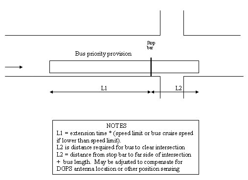
Figure 3-33. Bus Priority Provision Zone.
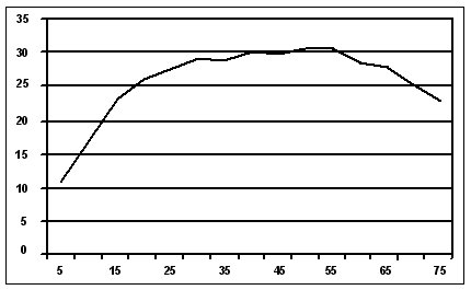
Figure 3-34. Fuel Economy as a Function of Vehicle Speed.
Vehicle Emissions
The Clean Air Act requires states to develop a state implementation plan (SIP) for each pollutant for which a nonattainment area violates the National Ambient Air Quality Standards (NAAQS). Transportation measures are a key component in SIP development. Depending on the severity of nonattainment, the CAA requires various transportation- related activities, programs and strategies. States also have the option of choosing among a variety of additional voluntary transportation measures that will best serve their needs. If these voluntary measures are included in a SIP, then they become enforceable under Federal law. As state and local transportation agencies will be required to implement these measures, it is vital that they take an active role in SIP development (82). The severity of measures required by the SIP depends on the level of nonattainment. An example of SIP requirements is shown in Table 3-20 (82).
The United States Environmental Protection Agency has mandated that the MOBILE6 (83) model be used for SIP development outside of California (84). MOBILE6 is an EPA approved emission factor model for predicting gram mile emissions from cars, trucks and motorcylcles under various conditions
Moderate <12.7 ppm:
|
Estimating Highway User Costs
Highway user costs are the total of:
- Vehicle operating costs,
- Travel time, and
- Accident costs.
Table 3-21 lists passenger car operating costs in the United States in 2003. Demonstrating the nation's reliance on highway transportation, in 1997 more than 182.7 million U.S. drivers drove more than 2.56 trillion vehicle miles in more than 211 million registered vehicles. In the same year, accidents killed 42,588 people, a rate of 1.66 deaths / 100 million vehicle miles. Tables 3-22 and 3-23 provide information on vehicle travel and accidents in 1990. Based on National Safety Council data, Table 3-24 shows accident cost rates for 2002.
Per Year |
Per Mile |
|
|---|---|---|
| Operating Costs | ||
| Gas and oil | -- | 7.2 cents |
| Maintenance | -- | 4.1 cents |
| Tires | -- | 1.8 cents |
| Cost per mile | -- | 13.1 cents |
| Insurance Costs | ||
| Comprehensive insurance | $203 | -- |
| Collision insurance ($500 deductible) | $401 | -- |
| Bodily injury and property damage ($100,000, $300,000, $50,000) | $498 | -- |
| License, registration, taxes | $205 | -- |
| Depreciation (15,000 miles annually) | $3,738 | -- |
| Finance charge (20% down; loan @ 9.0%/4 yrs.) | $744 | -- |
| Cost per year | $5,789 | -- |
| Cost per day | $15.86 | -- |
| Added depreciation costs (per 1,000 miles over 15,000 miles annually) | $181 | -- |
| 15,000 total miles per year | ||
| Cost per mile x 15,000 miles | $1,965 | -- |
| Cost per day x 365 days *** | $5,789 | -- |
| Total cost per year | $7,754 | -- |
| Total cost per mile* | 51.7 cents | -- |
| 20,000 total miles per year | ||
| Cost per mile x 20,000 miles | $2,620 | -- |
| Cost per day x 365 days *** | $5,789 | -- |
| Depreciation cost x 5 ** | $905 | -- |
| Total cost per year | $9,314 | -- |
| Total cost per mile* | 46.6 cents | -- |
| 10,000 total miles per year | ||
| Cost per mile x 10,000 miles | $1,230 | -- |
| Cost per day x 365 days **** | $5,190 | -- |
| Total cost per year | $6,420 | -- |
| Total cost per mile* | 64.2 cents | -- |
| * total cost per year ÷ total miles per year ** excess mileage over 15,000 miles annually (in thousands) *** ownership costs based on a 4-year/60,000-mile retention cycle **** ownership costs based on a 6-year/60,000-mile retention cycle Source: American Automobile Association, "Your Driving Costs," 2003. (See reference 85 for full details.) |
||
Table 3-22. Motor Vehicle Traffic Fatalities and Injuries — 1997
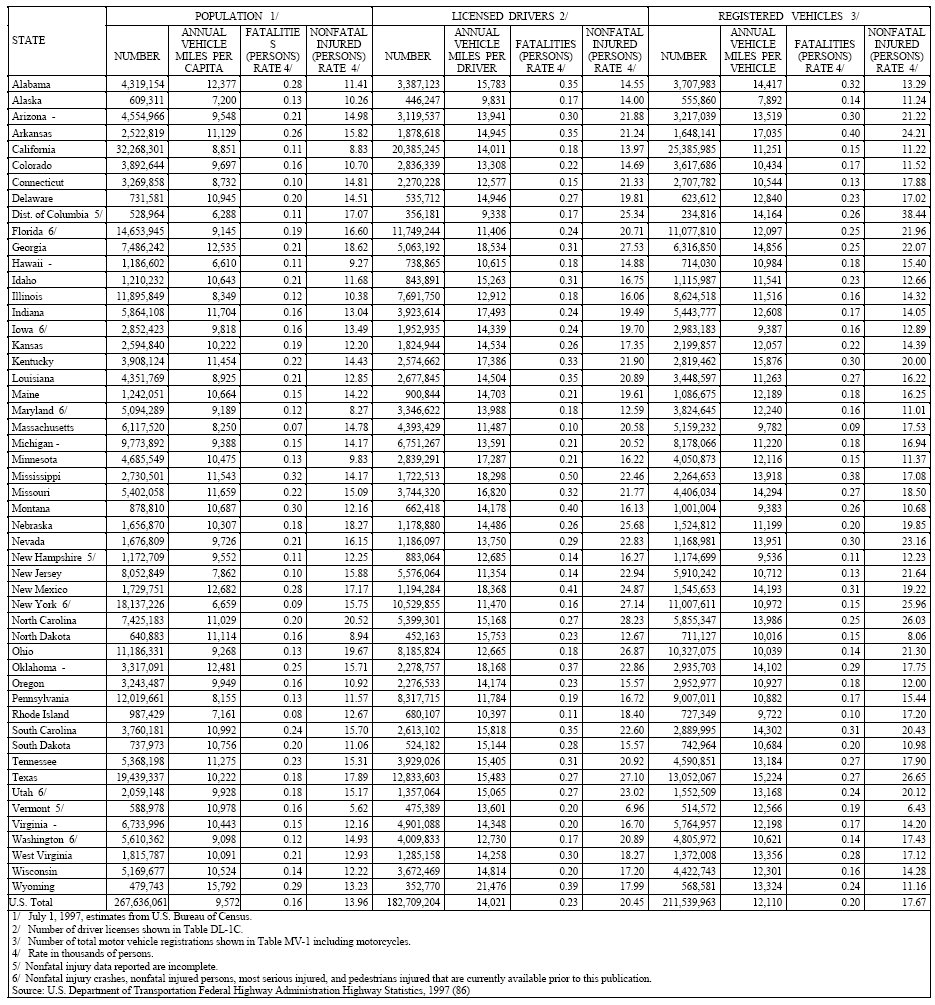
Table 3-23. Motor Vehicle Traffic Fatalities and Injuries By Highway
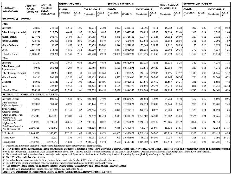
| Type | Cost |
|---|---|
| Fatal Accidents | $1,090,000 / death. |
| Non-fatal Disabling Accident | $39,900 / injury. |
| Property damage only Accident (including non-disabling injury) | $6200 / accident. |
| Source: National Safety Council (87) | |
Impacts of Traffic Signal System Improvement
The States of Texas, California, Virginia, North Carolina, Washington, and others have conducted comprehensive traffic signal system improvement programs. Percent improvement in overall average travel time, delay, or fuel consumption was the basis for evaluating the effectiveness of these projects.
Table 3-25 summarizes MOE improvement for the various traffic signal system improvement projects.
| Program / Items | Year | Fuel Reduction | Delay Reduction | Stop Reduction |
|---|---|---|---|---|
| TLS | 1992 | 9.1% | 24.6% | 14% |
| FETSIM | 1993 | 7.8% | 13.8% | 12.5% |
| Tyson's Corner, VA | 1999 | 9% | 22% | 6% |
| Seattle, WA MMDI | 1999 | 0.8% | 7% | 2.7% |
Project Level Impacts
The degree of improvement in overall traffic performance resulting from a given traffic signal improvement project depends, to a large extent on the control methods before project implementation. The more primitive the level and quality of the base condition, the greater the potential for improvement.
Fambro in cooperation with the Texas Governor's Energy Office and the U.S. Department of Energy (25) conducted an extensive evaluation of traffic signal improvement projects in Texas. Table 3-26 shows the overall MOE improvement. The evaluation shows that commitment to high quality signal timing efforts, including periodic updating of timing plans proves essential in all signal systems from the basic to the most advanced. The set it and forget it policy results in significant waste of the resources invested in traffic control systems.
| Coordination / Equipment Status | Percent Stops | Percent Delay | Percent Fuel Consumption |
|---|---|---|---|
| Uncoordinated arterial with existing equipment | 10 | 24 | 8 |
| Uncoordinated arterial with new equipment | 18 | 21 | 14 |
| Partially coordinated arterial with existing equipment | 6 | 9 | 3 |
| Partially coordinated arterial with new equipment | 15 | 18 | 3 |
| Coordinated arterial with existing equipment | 16 | 23 | 17 |
| Coordinated arterial with new equipment | 14 | 23 | 12 |
Network Impacts
Improving traffic signal operations, particularly on arterial streets, has powerful areawide impacts. With 166 projects completed in 8 large, 7 medium and 19 small cities, the Texas TLS Program realized benefits during the first year as shown in Table 3-27 (25).
| Size | Stops | Delay (hrs) | Fuel (gal) | Fuel (liter) | Savings ($) | Cost ($) |
|---|---|---|---|---|---|---|
| Large Cities | 1,283,099,850 | 30,621,657 | 22,180,341 | 83,952,590 | 346,360,309 | 2,885,302 |
| Medium Cities | 239,633,625 | 6,926,904 | 4,481,237 | 16,961,482 | 77,106,148 | 4,032,313 |
| Small Cities | 198,936,150 | 5,696,696 | 3,409,346 | 12,904,375 | 63,171,212 | 972,264 |
| Total | 1,721,669,625 | 43,245,257 | 30,080,724 | 113,855,540 | 486,637,668 | 7,889,879 |
As expected, the bulk of benefits occurred in large cities with the highest population and traffic volumes. However, substantial benefits also occurred in medium and small cities; the benefit / cost (B/C) ratio for small cities was 65:1. High values of B/C are obtained when capital expenditures for improvements are minimal.
The benefits for each intersection improvement depend on the before condition. For example, coordinating a series of isolated intersections generally produced greater benefits than retiming an existing coordinated system. Finally, note that signal timing optimization can increase delay or fuel consumption on side streets to improve flow along the arterial network. However, these increases in delay or fuel consumption often prove negligible in terms of total network improvement. Table 3-28 shows network improvement data from the TLS Program (25).
| Coordination / Equipment Status | Percent Stops | Percent Delay | Percent Fuel Savings |
|---|---|---|---|
| Uncoordinated network with existing equipment | 8 | 18 | 8 |
| Uncoordinated network with new equipment | 11.2 | 16.3 | 8.8 |
| Partially coordinated network with existing equipment | 4.4 | 20.5 | 8.7 |
| Partially coordinated network with new equipment | 16 | 26 | 11 |
| Coordinated network with existing equipment | 15 | 22 | 12 |
| Coordinated network with new equipment | 15 | 27 | 9 |
A more recent evaluation is the Seattle Metropolitan Model Deployment Initiative Evaluation (88). The following are highlights of the results of this project:
- Regional delay was reduced by 7% and the total number of stops decreased by 2.7%, while peak traffic volume increased by 0.2%.
- Because of the increase in traffic, there was very little improvement in the area of energy use and emissions.
- Overall, the expected number of crashes decreased by 2.5%, with the overall number of fatal crashes projected over a ten-year period reduced by 1.1%
Tables 3-29 and 3-30 show detailed information on the Seattle MMDI Evaluation:
| Measure per Average A.M. Peak Period, North Corridor Subarea | Baseline | ATMS | Change | % Change |
|---|---|---|---|---|
| Vehicle-Hours of Delay | 17,879 | 16,661 | -1,218 | -7.0% |
| Vehicle Throughput | 209,372 | 209,774 | +402 | +0.2% |
| Coefficient of Trip Time Variation | 0.242 | 0.237 | -0.005 | -2.1% |
| Vehicle-Km of Travel | 3,438,000 | 3,455,000 | +17,000 | +0.4% |
| Total Number of Stops | 1,200,000 | 1,167,000 | -33,000 | -2.7% |
| Measure per Average A.M. Peak Period, North Corridor Subarea | Baseline | ATMS | Change | % Change |
|---|---|---|---|---|
| Fuel Consumption (I) | 354,600 | 355,600 | +1,000 | +0.3% (NS) |
| HC Emissions (kg) | 390 | 392.6 | +2.6 | +0.7% (NS) |
| CO Emissions (kg) | 7043 | 7116 | +73 | +1.0% (NS) |
| Nox Emissions (kg) | 846.2 | 850.2 | +4 | +0.5% (NS) |
| (NS) = not statistically significant vs. baseline at 90% confidence level | ||||
Cost-Effectiveness Comparisons
Traffic signal system improvements rank as one of the most cost-effective urban transportation improvement actions. The following presents results of cost-effectiveness analyses of four different signal optimization programs at different locations and time periods.
- Optimization in Tysons Corner, VA, in 1999: Annual savings to motorists traveling the network were estimated at about $20 million. Stops were reduced by 6% (saving $418 thousand), system delay decreased 22% ($18 million), and fuel consumption decreased 9% ($1.5 million). Total annual emissions for CO, Nox, and VOC was decreased by 134,600 kilograms (89).
- FETSIM (Fuel Efficient Traffic Signal Management) between 1983 and 1993: The FETSIM Program involved 163 local agencies and 334 projects, improving 12,245 signals at a cost of $16.1 million, or $1,091 per signal. Results show reductions of 12.5% in stops, 13.8% in delay, 7.7% in travel time, and 7.8% in fuel consumption. The benefit / cost ratio is about 17:1 (90).
- TLS Program (Traffic Light Synchronization) in 1992: The TLS Program expended $7.9 million, approximately $3500/intersection (equipment purchase). It resulted in annual reductions in fuel consumption, delay, and stops of 9.1% ($30 million), 24.6% (43 million hours), and 14.2% (1.7 billion stops), respectively. The total savings to the public in the form of reduced fuel, delay, and stops was approximately $485 million in 1993. The benefit / cost ratio is about 62:1 (25)
- SSOS (Statewide Signal Optimization Squad) in North Carolina 1987:
- The SSOS Program average cost per retimed signalized intersection is $481,
- Each intersection annually saved 13,500 gallons of fuel, and $51,815 of operating costs, and
- The benefit cost ratio is about 108:1 (91).
- National Signal Timing Optimization (NSTO) Project by FHWA 1981: The NSTO Project cost $456 per intersection. At an average intersection each year, 15,470 vehicle-hours of delay were reduced, 455,921 vehicle stops were eliminated and 10,526 gallons of fuel were saved. The benefit / cost ratio is 63:1 (92).
3.11 Measures of Effectiveness
Any new or modified traffic control system should satisfy a goal or set of goals. The goal may explicitly state: reduce congestion in the core area of a city by minimizing stops and delays or pledge increase accessibility to downtown business. Goals may be easy to state, but difficult to measure.
Measures of effectiveness (MOE) provide a quantitative basis for determining the capacity of traffic control systems and their strategies to attain the desired goals. To successfully determine goal attainment, the MOEs must relate to the goals. Also, with no comparative analyses, measures must be compared with baseline values to determine the quality of goal attainment. Other desirable criteria for selecting MOEs include:
- Simplicity within the constraints of required precision and accuracy,
- Sensitivity to relatively small changes in control strategy implementation, and
- Measurability on a quantitative scale within reasonable time, cost, and manpower budgets.
- Common measures of effectiveness include:
- Total travel time,
- Total travel,
- Number and percentage of stops,
- Delay,
- Average speed,
- Accident rate, and
- Throughput.
These measures of effectiveness indicate the improvement in efficiency of traffic flow resulting from control.
Table 3-31 describes these MOEs and their calculation.
Several other important MOEs can be derived from those in the Table. Gasoline consumption and emissions, for example, can be computed from total travel time, stops, and delay (93).
| MOE | Description | Calculation |
|---|---|---|
| Total Travel Time | A primary MOE for evaluating freeway and urban street control systems and strategies. Expressed in vehicle-hours (veh-hr), it represents the product of the total number of vehicles using the roadway during a given time period and the average travel time of the vehicles. | The average travel time, ttj, in hours over a roadway section
is:
Where: Xj = Length of roadway section, in mi (km) and Total travel time, TTTj, in veh-hr over section j is: Where: Nj = Number of vehicles traveling over section j, during time period, Total travel time, TTT, in veh-hr, for all sections of a roadway is: TTTj = Total travel time for section j, in veh-hr |
| Total Travel | Another common MOE used to evaluate traffic operations. Expressed in units of vehicle-miles (veh-mi) (vehicle-kilometers (veh-km)), it represents the product of the total number of vehicles using the roadway during a given time period and the average trip length of the vehicles. | The total travel, TTj, in veh-mi, over a roadway section j is:
Where: Xj = Length of roadway section j, in mi (km) Equations 3.26 and 3.28 suggest that the total travel, TTj, in veh-mi (veh-km), over a roadway section j can be derived from total travel time and average speed for section j, as follows: Where: Total travel, TT, in veh-mi (veh-km), for all sections of a roadway is: Where: K = Number of roadway sections |
| Number and Percentage of Stops | Evaluates the quality of flow on urban streets. Stops may be obtained by floating vehicle methods or by direct observation of the intersection. Traffic control systems may have the capability to compute stops. | The calculation of the number of stops on an approach to an intersection is determined by the relationship between detector actuations and signal timing. A typical time-space diagram for number of stops computations is presented in Figure 3-35. The number of stops per cycle is the number of detector actuations that occur between Tgc and Trc. Trc is the last time that a vehicle can cross the detector during the green interval, and still clear the intersection without stopping. The values for Tgc and Trc are based on predetermined vehicle trajectories between the detector and the intersection. In some algorithms for computing number of stops, these trajectories remain the same for all vehicles, while in others they vary according to the number of vehicles already stopped between the detector and intersection. |
| Delay | Widely used MOE in traffic control. On urban arterials, delay is defined
as the increase beyond a travel time corresponding to a baseline speed (a
speed below which travel would be considered delayed).
For urban intersections, delay is commonly defined as the time lost at the intersection by those vehicles that are stopped. Box and Oppenlander describe a technique for manually obtaining stopped delay (94). |
For urban arterials, baseline travel time subtracted from measured total
travel time for the same time period. Where computer traffic control systems
compute delay, Figure 3-35 illustrates the computation of stopped-vehicle
delay. Assuming all stopped vehicles clear the intersection on the next
green, the delay Di, in seconds, for the ith stopped vehicle is determined.
Where: R = Length of the red interval, in seconds Time, tci, is determined from the time, taj, at which the ith vehicle actuates the detector and a predetermined approach trajectory. Time, tdj, is determined from time, Tg, at which the next green interval begins and- a predetermined departure trajectory. Some algorithms used to compute stopped-vehicle delay provide for varying the predetermined approach and departure trajectories according to the number of vehicles already stopped. Assuming all stopped vehicles clear the intersection on the next green, total stopped-vehicle delay, D, in seconds, for a cycle is determined by: Where: Di = The delay of the ith vehicle stopped during the cycle, in seconds Algorithms based on these concepts may be subject to the following additional sources of error: • Vehicles making right-turns-on-red may not be properly accounted for • The algorithm might not properly handle saturated intersections |
| Average Speed | One of the most descriptive variables of freeway traffic flow. Point samples of average stream speeds or the speed traces of individual vehicles can locate problem areas and provide useful data for developing other performance measures (93). | Manually, by radar or laser guns. See Table 3-1 for calculations from system detectors. |
| Accident Rate | Accident rate improvement is a common goal for traffic control systems. Rates for intersections usually are expressed in terms of accidents per million entering vehicles. Freeway accident rates are often expressed in accidents per 100 million vehicle miles. | Box and Oppenlander describe techniques- for determining the statistical significance of accident data (94). |
| Throughput | Although its dimension is equivalent to speed, throughput is usually used
in a somewhat different way. Figure 3-36 shows plots of throughput for a
baseline system (curve A) and an improved traffic control system (curve
B). These plots represent a best mathematical fit of the data represented
by individual sets of measurements. Throughput is represented by the slope
of the line to a point on the curves. As traffic demand increases, the throughput
begins to decrease.
This approach enables the traffic engineer to more precisely measure results relative to goals. For example, if the goal is to improve congested traffic conditions, examination of curve B in the congested region indicates only marginal improvement. This might lead the traffic engineer to consider strategies to specifically target to this region (section 3.8). |
 for one or more traffic conditions |
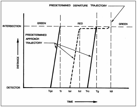
Figure 3-35. Time-space Diagram for Stop and Delay Computations for Urban Street Control.
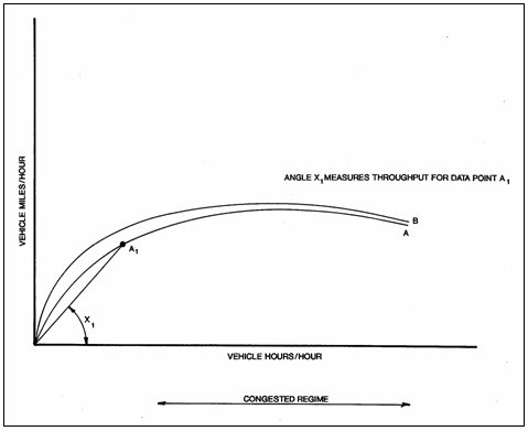
Figure 3-36. Throughput and Component MOEs.
In many cases, these MOE are measured independently of traffic control system data. Box and Oppenlander (94) provide techniques and sample size requirements for performing many of these studies.
In some cases, these studies may use data generated by the traffic system. It then becomes important to:
- Identify the measurement error for these variables, and
- Specify and collect a sample size which assures statistically significant results.
Evaluation procedures must also consider the demand element. The evaluation must account for:
- Changing traffic demands between the before and after period,
- Other factors such as weather.
Complete list of references for Chapter 3.
Next | Previous


